
Classic Schematics

The provided schematics encompass a variety of electronic designs that may include circuit diagrams, component layouts, and functional descriptions of various electronic systems. These documents serve as valuable resources for engineers, hobbyists, and students seeking to understand or replicate specific circuit designs.
The schematics may cover a range of applications, such as audio amplifiers, power supplies, microcontroller interfaces, and more. Each schematic typically includes symbols representing electronic components such as resistors, capacitors, diodes, transistors, and integrated circuits. Additionally, the interconnections between these components are illustrated through lines that indicate electrical connections.
To ensure effective utilization of these schematics, it is important to understand the notation and symbols used within each document. For example, standard electronic symbols follow conventions established by organizations such as the Institute of Electrical and Electronics Engineers (IEEE). Familiarity with these symbols allows for easier interpretation and implementation of the designs.
Moreover, the inclusion of component values, power ratings, and operational parameters is essential for successful circuit construction. These details provide critical information for selecting appropriate components and ensuring that the circuit operates within its intended specifications.
In cases where larger GIF files do not render properly in web browsers, a recommended approach is to download the files directly to a local device. This method not only preserves the integrity of the schematic but also allows for offline viewing and analysis, which can be particularly beneficial for detailed examination and troubleshooting.
Overall, the collection of schematics aims to serve as a comprehensive reference for individuals engaged in electronic design and experimentation, fostering knowledge sharing and innovation within the electronics community.Here`s some schematics and information that can be hard to find elsewhere. If you have some schematics that you think belongs among these, please do not hesitate to contact me. I hope to be able to extend this little collection with time, so check back for updates. NOTE: Some of the larger. gif-files dosen`t show correctly in some browsers. If you have that problem, instead "right-click" on the link and select "save target as. " to save to your harddisk - and view it from there. 🔗 External reference
Related Circuits
The panels appear to be well-designed, and the cases are tidy. It is noted that the cases are constructed from MDF board. The panels are recessed significantly, likely to provide protection for the knobs. There is curiosity regarding the...
Approximately 20 years ago, it was common to encounter small key-holders that emitted an intermittent beep for a few seconds after the owner whistled. These devices utilized a specialized integrated circuit (IC) and were not suitable for home construction....
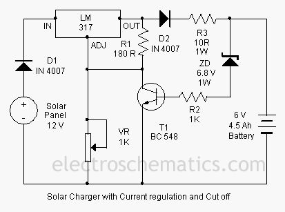
This is a solar charger circuit designed to charge Lead Acid or Ni-Cd batteries utilizing solar energy. The circuit captures solar energy to charge a 6-volt, 4.5 Ah rechargeable battery for various applications. It includes voltage and current regulation,...
Hello everyone, my name is Mike, and I come from a small country called New Zealand. I am currently planning to build a 6L6 push-pull stereo power amplifier and preamplifier. The project involves designing a 6L6 push-pull stereo power amplifier,...
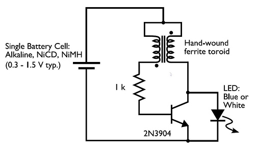
In the circuit diagram for the Joule Thief, the common point of the toroid is the connection at the top of the hand-wound ferrite toroid, located in the upper right of the diagram. This connection leads to the positive...
A FET impedance converter is designed for use with the Fishman pickup on a Kay orchestra bass. The circuit is divided into two sections, allowing the input section to be mounted inside the head shell of a 1/4" plug,...