
Closed-Loop Peak Detector Circuit

The closed-loop peak detector circuit is designed to capture and hold the peak value of an input signal, ensuring that the output accurately reflects the maximum amplitude of the waveform. The inclusion of a Schottky diode in the feedback loop is critical for maintaining precision, as this type of diode has a low forward voltage drop and fast switching capabilities. This enhances the responsiveness of the circuit to rapid changes in the input signal.
The 20-ohm resistor, labeled RQ, plays a crucial role in isolating the load from the detection circuit, which is vital for stability. By preventing oscillations, RQ ensures that the output remains steady and accurate, particularly in dynamic environments where the input signal may vary significantly.
The use of a digital voltmeter (DVM) for reading the DC value allows for precise measurements, making it suitable for applications where accuracy is paramount. The performance of the peak detector is frequency-dependent; at lower frequencies, the decay of the capacitor charge between cycles is manageable, leading to minimal error. However, as the frequency increases, the time available for the capacitor to charge diminishes, resulting in increased error margins. This effect is particularly pronounced at high frequencies, where the operational amplifier's slew rate becomes a limiting factor. The slew rate defines how quickly the output of the op-amp can change in response to a rapid input signal, and when the frequency approaches 4 MHz, the limitations become significant enough to cause a noticeable rise in error.
Overall, this closed-loop peak detector circuit is an effective solution for accurately capturing peak values in high-frequency applications, provided that careful consideration is given to component selection and circuit design to mitigate the effects of frequency-related errors. This closed-loop peak detector circuit uses a Schottky diode inside feedback loop to obtain good accuracy. The 20- resistance RQ isolates the 0.01- load and prevents oscillation. The dc value is read with a DVM. At a low frequency, the error is small and dominated by the decay of the detector capacitor between cycles.
As the frequency rises, the error increases because capacitor charging time decreases. During this time, the overdrive becomes a very small portion of a sine-wave cycle. Finally, at approximately 4 MHz, the error rises rapidly because of the slew- rate limitation of the op amp.
Related Circuits
Many households are still equipped with tube-type television sets. If there is a desire to connect one of these large televisions to a stereo system to enhance the sound quality... To connect a tube-type television to a stereo system, it...
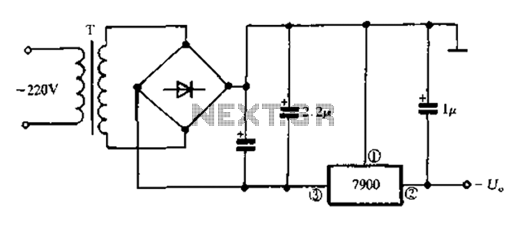
7900 series three-terminal fixed negative output voltage regulator circuit The 7900 series comprises a range of three-terminal fixed negative voltage regulators designed to provide stable output voltages. These regulators are specifically engineered to deliver a consistent output voltage, which is...
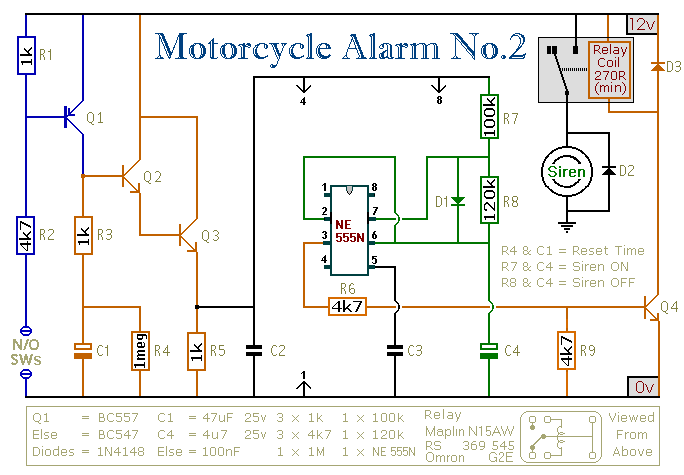
This circuit provides an intermittent siren output with an automatic reset function. It can be manually activated using a key switch or a concealed switch, and it can also be configured to engage automatically when the ignition is turned...
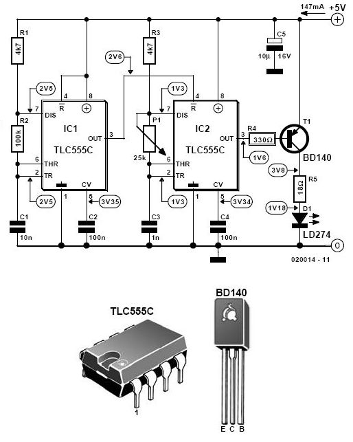
This infrared alarm barrier is designed to detect individuals passing through doorways, corridors, and small gates. The transmitter emits a beam of infrared light that is invisible to the human eye. When the light beam is interrupted by a...
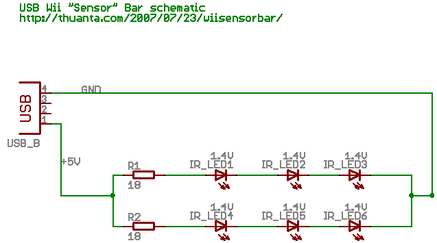
The following circuit illustrates the Wii "Sensor" Bar Project Circuit Diagram. Features include a series of infrared LEDs positioned at both ends of the bar, which emit infrared light. The Wii Sensor Bar is a crucial component for the Wii...
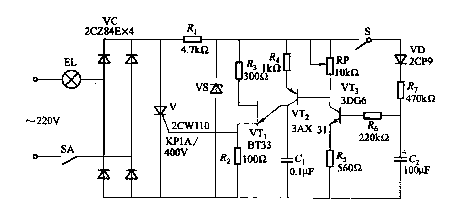
A fade-in fade-out light switch enables gradual adjustments in lamp brightness, allowing the light to turn on and off smoothly. When the switch SA is closed, the lamp brightness increases from dim to bright. Conversely, when the switch SA...