
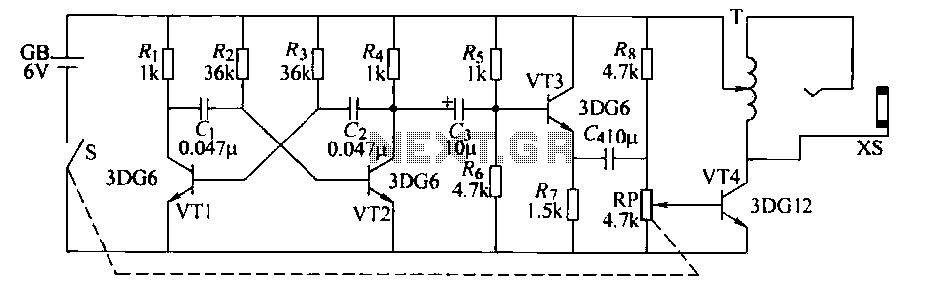
TV Muter Circuit

To connect a tube-type television to a stereo system, it is essential to understand the audio output options available on the television. Most older tube televisions typically have analog audio output options, such as RCA connectors (red and white plugs) or a 3.5mm headphone jack. The connection process will vary depending on the available outputs on the television and the inputs on the stereo system.
1. **Identify Output Types**: Check the back of the tube television for audio output ports. Look for RCA jacks labeled as "Audio Out" or a headphone jack.
2. **Select Appropriate Cables**: If the television has RCA outputs, use an RCA to RCA cable to connect to the stereo system. For a headphone jack, a 3.5mm to RCA cable can be utilized.
3. **Establish Connections**:
- For RCA outputs: Connect the red plug to the red input (right audio channel) and the white plug to the white input (left audio channel) on the stereo system.
- For a headphone jack: Connect the 3.5mm plug to the headphone output of the television and the RCA ends to the corresponding inputs on the stereo system.
4. **Adjust Audio Settings**: Once the physical connections are made, turn on both the television and the stereo system. Adjust the volume levels on both devices to ensure optimal sound quality. If the television has an audio output setting, ensure it is enabled.
5. **Testing**: Play content on the television and listen for sound through the stereo system. Adjust the balance and equalization settings on the stereo to enhance sound quality further.
This connection method allows for improved audio performance from a tube television, utilizing the capabilities of a modern stereo system to deliver a richer sound experience.Many households are still graced by tube-type television sets. If you want to connect one of these large tellies to your stereo system to improve the soun.. 🔗 External reference
Related Circuits
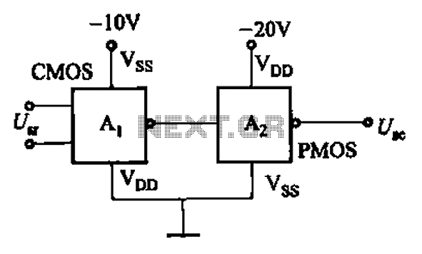
CMOS and PMOS cross interface circuit with PMOS integrated circuit providing high input impedance, allowing the input current to be negligible. The CMOS and PMOS interface circuit is illustrated in the accompanying figure. The CMOS and PMOS cross interface circuit...
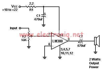
A simple audio amplifier can be designed using the LM380 along with a few external components. This amplifier features a wide supply voltage range, an input impedance of 150 kΩ, low distortion, and a current capability of 1.3 A. The...
An H-bridge is a type of circuit utilized for controlling the direction (and occasionally the speed) of an electric motor by employing a single polarity voltage. The circuit functions by reversing the current flow to change the motor's rotation...
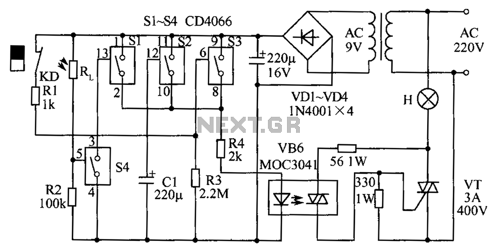
The circuit diagram illustrates a group of four analog electronic circuit switches (S1 to S4). Switches S1, S2, and S3 are utilized in a parallel delay circuit. When the power is activated, resistor R4 drives the triac VT, which...
The saying goes "dead ringworm surgical, medical dead asthma." This example describes an electronic anti-asthmatic device that produces high-voltage stimulation pulses, which can serve as an adjunct therapy for patients suffering from cough. The circuit consists of a self-excited...
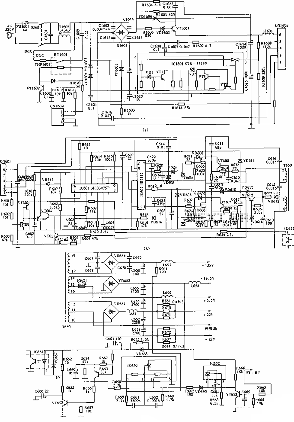
The circuit of the Sony KV-S29MHl (S Movement series) TV switching power supply (SIR a 80145A) consists of three main sections: (A) the power oscillation part, (B) the regulator part, and (C) the output section. The Sony KV-S29MHl TV switching...