
cm7777 preamp

To troubleshoot the CM7777 preamp, it is essential to perform a systematic check of both the power supply and the preamp circuitry. Begin by measuring the output voltage of the power supply with a multimeter. Ensure that the power supply is connected correctly and powered on. The expected output voltage should align with the specifications provided in the CM7777 datasheet, typically around 12V DC for proper operation. If the voltage is absent or significantly lower than expected, this indicates a potential fault within the power supply.
Next, if the power supply is functioning correctly, the next step is to examine the preamp itself. This involves checking for any obvious signs of damage, such as burnt components or broken traces on the circuit board. Utilize the multimeter to test the continuity of critical components, including resistors, capacitors, and the integrated circuit. It may also be beneficial to inspect the power connections to the preamp to ensure they are secure and free from corrosion.
If the preamp is receiving the correct voltage but still fails to operate, further analysis of the internal components may be required. This could include testing the gain stages and verifying the integrity of any active components such as transistors or operational amplifiers within the preamp circuit.
In conclusion, a methodical approach to testing both the power supply and the preamp will help isolate the source of the failure, facilitating effective repairs or replacements as necessary.My CM7777 preamp has failed. I want to determine if the failure is due to the power supply or the preamp itself. Does the power supply output a DC voltage on the .. 🔗 External reference
Related Circuits
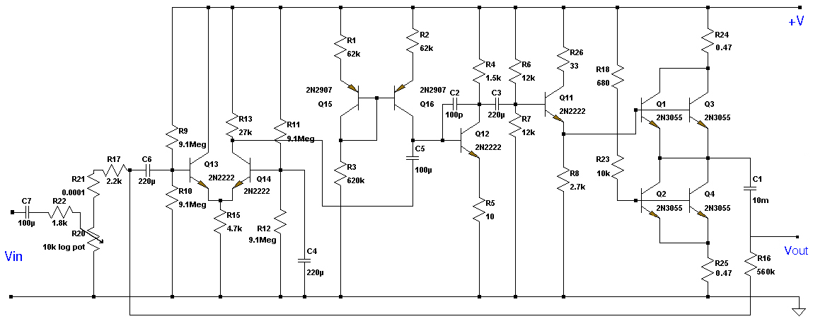
This Class A preamplifier features a symmetrical design. The input differential stages utilize dual transistors, T1 and T2. Polarization correction is crucial due to amplification discrepancies and is managed by transistor T12. Potentiometer P2 adjusts the output voltage to...
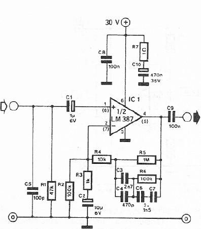
A dynamic microphone preamplifier can be constructed using the LM387 dual operational amplifier integrated circuit. The input impedance is approximately 47k ohms, primarily determined by resistor R1. If a dynamic microphone with a different impedance is to be connected,...
The circuit is a preamplifier with digital regulation intensity of sound. It is separated into three departments. The first schematic (Fig.1) shows the control circuit of the electronic potentiometer. The control is achieved through two pressing switches. The S1...
This is a specialized low-voltage version of an audio preamplifier. The emitter voltage of transistor T1 is biased close to half the supply voltage (1.5V) to enable maximum output voltage swing. Both transistors are directly coupled and utilize closed-loop...
Soundblaster soundcard series (SB16, SB32, AWE32 and AWE64) have all a microphone input designed to be used with the electret microphones which come with the soundcard package (some packages) or with separate microphone designed to be used with SoundBlaster...
This circuit is designed to work at UHF frequencies in the range 450-800MHz. It has a gain of around 10dB and is suitable for boosting weak TV signals. The circuit is shown below. The described circuit operates within the Ultra...