
Audio Preamplifier with Digital Volume

Additional Content: The preamplifier circuit begins with a control circuit for an electronic potentiometer, depicted in Fig.1. This control mechanism is managed by two switches: S1, which increases the sound intensity, and S2, which decreases it. These switches operate an oscillator that adheres to a bistable multivibrator R-S (ICIC-D), a component that influences the direction of counter IC3.
The IC2B gate plays an essential role in this circuit by ensuring the counter is deactivated when it reaches the boundaries of the regulation region. This function prevents any over- or under-regulation of the sound intensity, maintaining the audio output within a desirable range.
Another key feature of this preamplifier circuit is the S4 switch. This switch allows the user to select a specific sound level that the system will revert to after a RESET or when the circuit is powered. This function provides a user-friendly interface for sound control, ensuring the audio output can be easily adjusted to suit the user's preference.
The circuit also includes a null sound level selection feature, which can be activated using the S3 switch. This feature allows the user to quickly mute the sound, providing a fast and efficient method of controlling the audio output. This circuit, therefore, offers a comprehensive solution for sound intensity regulation, combining a variety of features to deliver a user-friendly, efficient, and effective preamplifier.The circuit is a preamplifier with digital regulation intensity of sound. He is separated in three departments. In first schematic (Fig.1), is found the circuit of control of electronic potesometer. The control become from two pressing switches. The S1 (UP), that put up the intensity of sound and the S2 (DOWN), on the contrary, that lower the intensity, checking them two oscillator follow a bistable multivibrator R-S (ICIC-D), with that determined the direction of counter IC3.. The gate IC2B ensure deactivate the counter in the limits of region of regulation. With the S4 we have the possibility selecting the level of sound, in which it will come back after RESET or when we give supply in the circuit.
This operation is very useful when we select null level of sound, then with switch S3 we have the possibility of going to situation MUTE, to rapid nihilism of sound. 🔗 External reference
Related Circuits
This application note describes the evaluation board for the AD7892-2, a 12-bit analog-to-digital (A/D) converter. The AD7892-2 is a high-speed, low-power device capable of 500 ksps sampling rate, operating from a single +5V supply. It features an on-chip track/hold...
Digital step-kilometer counter with a maximum range of 9,950 meters, displayed using two digits. The device can be conveniently placed in a pants pocket for use during walking and jogging activities. Circuit components include resistors R1 and R3, each...
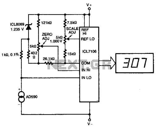
The ICL8069 brings the input within the common-mode range, while the 5 k ohm pots trim any offset at 218° (-55°C) and set the scale factor. This circuit allows for zero adjustment as well as slope adjustment. The ICL8069 is...
This article discusses the creation of a digital thermometer using the Arduino Uno. The temperature sensor employed is the LM35DZ, although it can be substituted with other sensors like the DS18B20. The sensor detects temperature and sends the data...
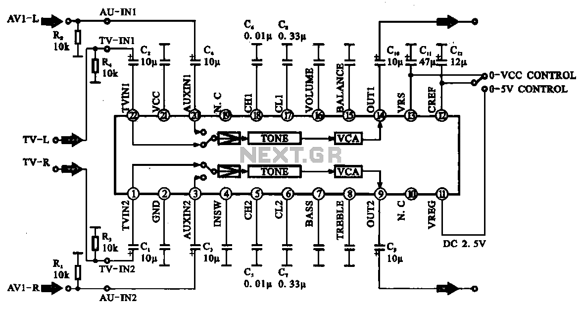
Audio signal control circuit. It illustrates a typical audio signal control circuit where two audio signals enter the integrated circuit through switching and tone controls (treble and bass), subsequently adjusting the output sent to the audio power amplifier. The audio...
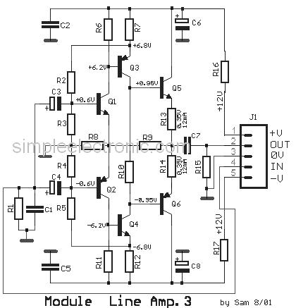
This is a simple low-impedance preamplifier circuit diagram used to amplify an audio signal. The circuit operates with a 12V DC power source and is straightforward due to its minimal component count. The low-impedance preamplifier circuit is designed to enhance...