
UHF Preamplifier

The described circuit operates within the Ultra High Frequency (UHF) band, specifically targeting frequencies from 450 MHz to 800 MHz. This frequency range is commonly utilized for television broadcasting, particularly for digital and analog TV signals. The primary function of the circuit is to amplify weak signals to a more usable level, thereby improving the quality of reception.
The circuit achieves a gain of approximately 10 dB, which indicates a tenfold increase in signal power. This level of amplification is typically sufficient for compensating for signal losses that may occur due to distance from the transmission source, obstacles, or interference from other electronic devices.
Key components of the circuit likely include a low-noise amplifier (LNA) designed to minimize additional noise during the amplification process, ensuring that the integrity of the original signal is maintained. The LNA is typically followed by a matching network that optimizes the impedance to maximize power transfer between the circuit stages and the antenna.
Power supply considerations are also critical in the design. The circuit may utilize a regulated power supply to ensure stable operation, particularly since fluctuations in voltage can affect the performance of the amplifier. Additionally, bypass capacitors are often included to filter out any high-frequency noise from the power supply.
The circuit layout is crucial for performance, and careful attention should be paid to the placement of components to minimize parasitic inductance and capacitance. Shielding may also be implemented to protect the circuit from external electromagnetic interference (EMI), which is particularly important in the UHF range.
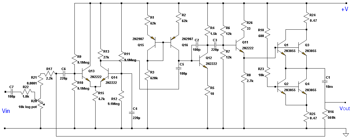
Overall, this circuit serves as an effective solution for enhancing the reception of UHF signals, making it a valuable component in television and communication systems where signal strength is a critical factor.This circuit is designed to work at UHF frequencies in the range 450-800MHz. It has a gain of around 10dB and is suitable for boosting weak TV signals. The circuit is shown below. 🔗 External reference
Related Circuits
This preamplifier is designed for low-resistance sources such as moving coil heads (MC). The circuit employs three parallel double transistors, SSM2220 or MAT03, which form a differential amplifier that minimizes noise. When connected to an OP27 amplifier, it further...
The amplifier drives a pair of loudspeakers using two LM3876 integrated power amp ICs (50 watts per channel), or a pair of headphones via a Meier crossfeed filter and an OPA2134 dual opamp. It provides four switchable line level...
The microphone preamplifier circuit design presented in this schematic utilizes the SSM2015 component manufactured by Precision Monolithics Inc. (PMI). This component provides high amplification with low noise characteristics (1.3nV/f). The design is configured to handle differential input signals and...
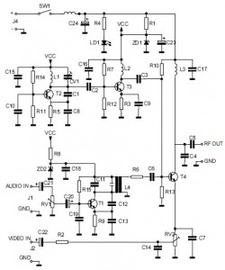
This is the circuit diagram of an audio/video modulator. The circuit converts audio and video signals into a UHF TV signal, allowing a video signal from a camera or other source to be connected to a standard TV set....
This Class A preamplifier features a symmetrical design. The input differential stages utilize dual transistors, T1 and T2. Polarization correction is crucial due to amplification discrepancies and is managed by transistor T12. Potentiometer P2 adjusts the output voltage to...
Simple circuitry suitable for moving-magnet cartridges. Passive high-frequency equalization. This simple but efficient circuit devised for cheap moving-magnet cartridges can be used in connection with the audio power amplifiers shown in these webpages, featuring low noise, good RIAA frequency...