
Mini Metronome by 555 Timer/Oscillator IC

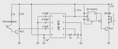
The described mini metronome circuit utilizes an integrated circuit (IC1) that serves as the core timing element, generating a pulse signal at variable frequencies corresponding to the selected beats per minute (BPM). The operational range from 40 to 208 BPM allows for versatile applications, from practice sessions for musicians to tempo guidance for various rhythmic activities.
Transistors Q1 and Q2 are configured in a manner that enables them to modulate the output frequency of IC1 linearly. This configuration can be achieved through a feedback mechanism where the transistors adjust the charge and discharge times of a timing capacitor, which is connected to the IC. The precise control of these transistors ensures that the BPM can be adjusted smoothly without abrupt changes, providing a stable and reliable tempo.
The circuit may also include additional components such as resistors and capacitors to set the timing characteristics of IC1. A potentiometer could be incorporated to allow users to fine-tune the BPM setting easily. Furthermore, an LED indicator may be added to visually represent the tempo, flashing in sync with the output beats.
Power supply considerations are essential for the circuit, with a typical requirement of a stable voltage source, often provided by batteries or a DC power supply. Proper decoupling capacitors should be placed near the power pins of IC1 to minimize noise and ensure stable operation.
Overall, this mini metronome circuit is an effective tool for maintaining tempo, and its straightforward design allows for easy assembly and modification, making it suitable for both hobbyists and professional applications in music and rhythm training.This mini metronome gives a linear scaled output and 40 to 208 beats per minute. 1- Q1 and Q2 transistors provide linear frequency variation of IC1 depend.. 🔗 External reference
Related Circuits
The 555 timer can be utilized to reduce the cost of incorporating a triggered sweep into an economical oscilloscope. The timer is activated by the input operational amplifier of the circuit. The application of the 555 timer in an oscilloscope...

A few months ago, a compact and effective alarm was designed with the following requirements: simple construction, reliable operation, low power consumption, and a small size. Initially, CMOS logic gates were considered, but this approach was abandoned due to...

The super dimmer is an improved version compared to the standard dimmer currently in use. Testing its performance will provide a clearer understanding of its advantages. The super dimmer operates using advanced technology that allows for finer control over...
A circuit diagram for a mini battery-powered version of roulette is presented. This circuit utilizes a 4017 decade counter (IC2) to drive 10 LEDs. Only one LED is illuminated at any given time, which is managed by a common...
A simple circuit diagram illustrates a schematic for a remote control system, which consists of two parts: the transmitter and the receiver. The transmitter circuit is controlled by an NE555 integrated circuit (IC) and operates by detecting the emitted...
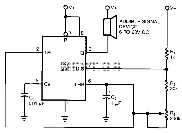
The simple circuit converts the continuous beep of an audible-signal device, such as a Mallory sonalert, into a unique warble or chirp. The values of resistor R and capacitor C2 determine the specific tone quality produced. With a 1kΩ...