
Cmos Pair 2-Mhz Crystal Oscillator

The 2 MHz crystal oscillator circuit employs complementary metal-oxide-semiconductor (CMOS) technology, which is known for its low power consumption and high noise immunity. The core of the circuit consists of a quartz crystal that provides a stable frequency reference, ensuring precise timekeeping in digital watches and clocks.
The CMOS pair in the circuit typically includes two transistors configured in an inverter arrangement. This configuration allows for efficient oscillation, with one transistor driving the other, creating a feedback loop that sustains the oscillation at the desired frequency. The choice of a 2 MHz frequency is particularly advantageous for timekeeping applications, as it strikes a balance between accuracy and power efficiency.
Additionally, the circuit may incorporate passive components such as resistors and capacitors to fine-tune the oscillation characteristics and stabilize the output signal. The low power drain characteristic of this circuit is essential for battery-operated devices, extending the operational life of digital watches and clocks.
In summary, the 2 MHz CMOS crystal oscillator circuit is an effective solution for timekeeping applications, combining low power consumption with reliable frequency generation, making it an ideal choice for modern digital timepieces.This is a 2 MHz crystal circuit using CMOS pair. This circuit is ideal for uses in digital watches and clock because this circuit has low power drain. The.. 🔗 External reference
Related Circuits
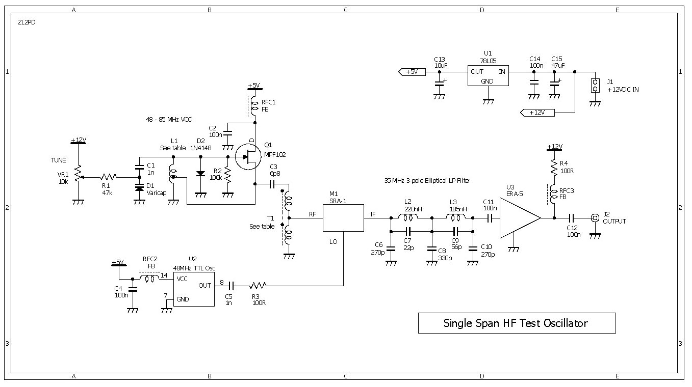
This compact RF oscillator operates across the entire frequency range of 0.4 to 30 MHz in a single sweep of the dial, featuring a terminated 50-ohm output of more than 300 mV throughout the HF band. Unlike most signal...
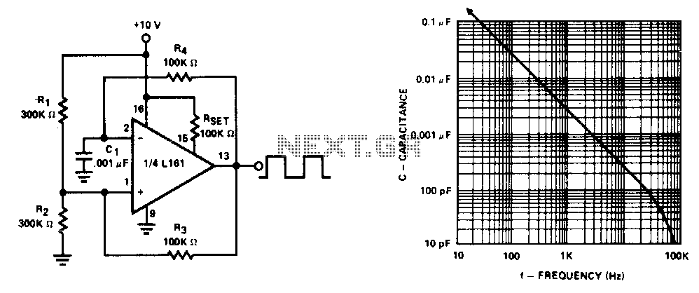
This generator operates at frequencies exceeding 100 kHz. The lower frequency limit is determined by capacitor Cl. Additionally, the frequency remains constant for supply voltages down to +5 V. The generator described is a versatile electronic oscillator capable of producing...
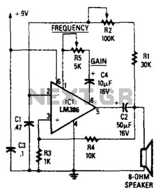
The circuit's frequency oscillation is given by the formula f = 2.8 / [Cix(i1 + i2)]. By utilizing the specified values, the output frequency can be adjusted from 60 Hz to 20 kHz by rotating potentiometer R2. A portion...
Many radio amateurs are interested in powering simple radio receivers using "free energy," which refers to energy obtained directly from the air via the receiver antenna. The circuits described can facilitate radio reception through a loudspeaker. However, questions remain...
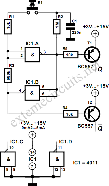
Using just two NAND or inverter gates, it is possible to build a D-type (or toggle) flip-flop with a push-button input. At power-up, the output of gate N2 is at a logical 1, ensuring that transistor T2 is switched...
The circuit presented is a standard Colpitts oscillator, commonly utilized in many amateur radio homebrew transmitters. This specific circuit is designed to operate effectively within a frequency range of 1500 kHz to 8000 kHz. To accommodate lower frequencies, it...