
Cmos touch switch

The circuit operates as a touch-sensitive switch, suitable for battery-operated devices. The core of the design is based on a Schmitt trigger, which is a type of comparator with hysteresis, allowing for stable switching behavior. IC1 generates a 100 kHz square wave oscillator signal, which serves as the basis for detecting touch input.
The output from IC1 is fed into IC2a, which is configured to operate in the linear region. This configuration allows IC2a to amplify the oscillator signal effectively. The amplified signal is then used to charge capacitor CI through a diode, ensuring that the charging process is unidirectional and protecting the circuit from reverse current.
IC2b functions as a level detector, monitoring the voltage across CI. When the touch sensor is activated, it introduces a capacitive load that significantly attenuates the oscillator signal. This attenuation leads to a rapid discharge of CI, which in turn alters the voltage level detected by IC2b. The change in state of IC2b can be used to trigger further actions in the circuit, such as turning on an LED, activating a relay, or interfacing with a microcontroller.
The design is advantageous for applications requiring a simple and reliable touch interface without the need for direct mains power, making it ideal for portable electronic devices. The use of a Schmitt trigger ensures that the circuit is less susceptible to noise and provides a clear transition between on and off states. Overall, this touch switch circuit represents an efficient solution for modern user interface applications.This touch switch does not rely on mains hum for switching-It-can be used with battery powered circuits. Schmitt trigger IC1 forms a 100 kHz oscillator and IC2a which is biased into the linear region, amplifies the output and charges CI via the diode.
IC2b acts as a level detector When the sensor is touched, the oscillator signal is severely attenuated which causes CI to discharge and IC2b to change state.
Related Circuits
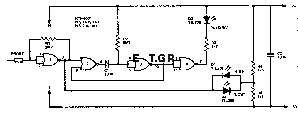
The logic probe can indicate four input states, as follows: floating input - all LEDs off; logic 0 input - D2 switched on (D3 will briefly flash on); logic 1 input - D1 switched on; pulsing input - D3...
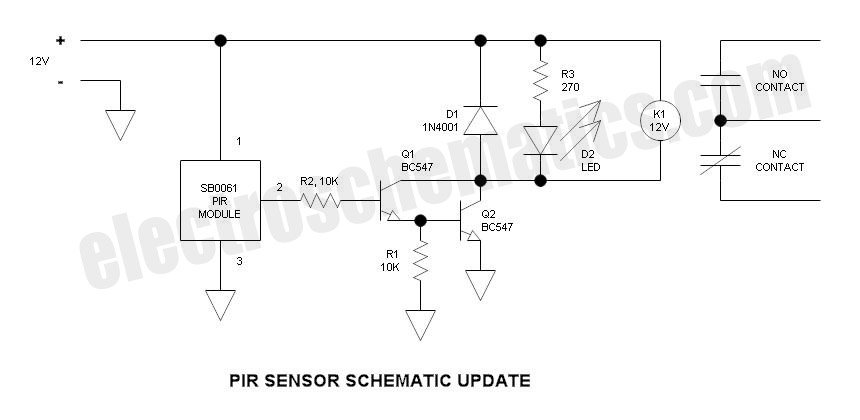
This is an update to Mr. Hareendran's PIR Sensor Security Light circuit. It has a limitation that restricts the relay voltage to approximately 3.3V. While this may work with some 5V relays, it is not compatible with all. The...
Speaker relay delay controlling circuit for audio amplifier The speaker relay delay controlling circuit is designed to manage the connection of speakers to an audio amplifier, ensuring that the speakers are activated only after a specified delay. This delay serves...
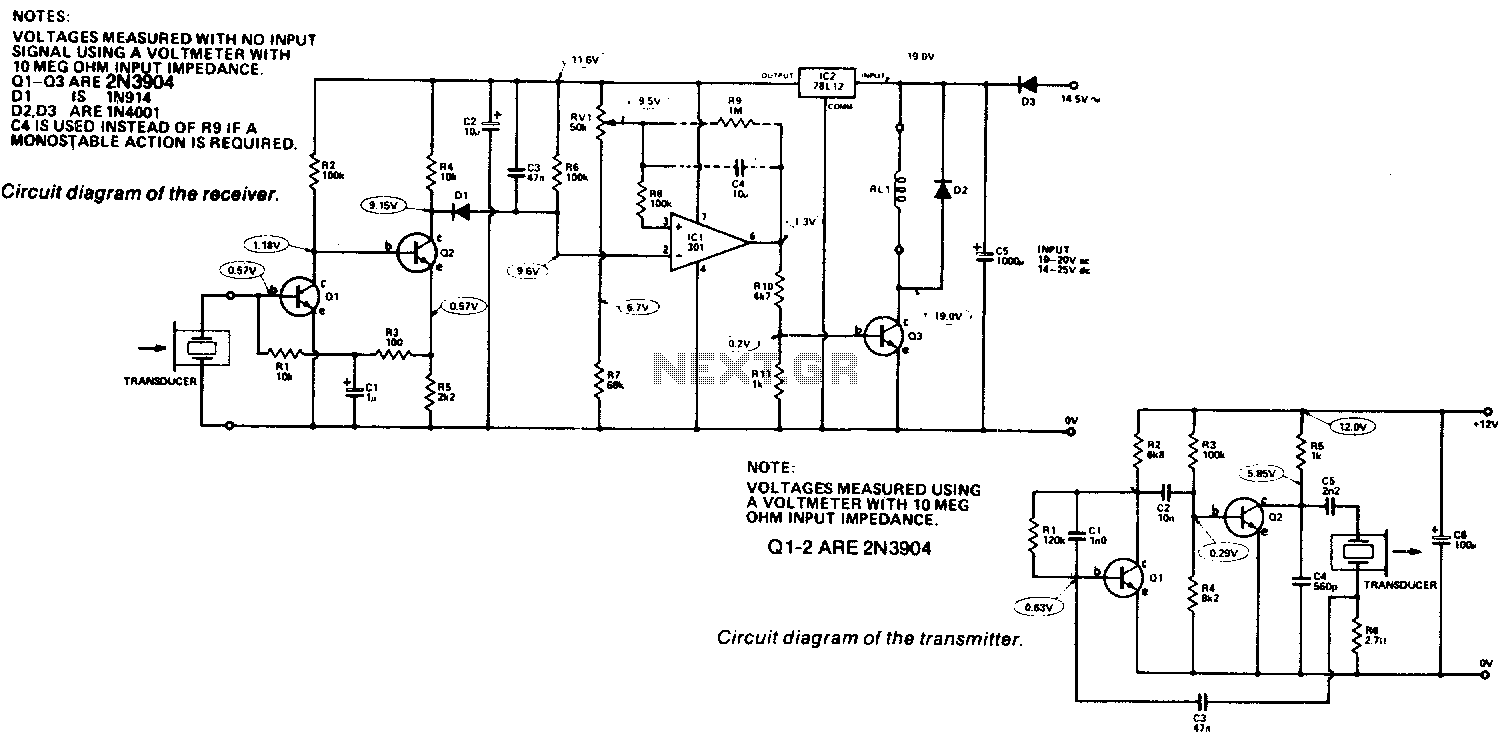
Receiver. The output from the transducer is amplified by Q1 and Q2, and rectified by D1. The voltage on pin 2 of IC1 will become more negative as the input signal increases. IC1 is utilized as a comparator, comparing...
For this special Halloween project, a spooky candy bowl was created that lights up when an unsuspecting trick-or-treater reaches in. While similar devices exist, many utilize complicated proximity sensors. The approach taken here is simpler, making it a suitable...
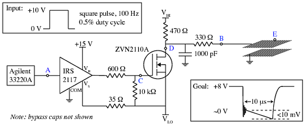
A copper mesh measuring 10 cm x 10 cm is situated in a vacuum chamber and connected to a BNC connector via a 24 cm copper wire. The objective is to rapidly switch the voltage across the mesh (referenced...