
voltage MOSFET Switch w/ Fast Settle Time for Switching E-Field

To simulate the mesh, a 24 cm wire was soldered to a piece of copper-clad perf board and linked to the circuit output at Point B. The signal was probed on the perf board using a Tektronix probe (500 MHz, 8.0 pF, 10 MΩ, 10x) connected to a Tektronix TDS3012 100 MHz digital oscilloscope. Observations indicate that the switching is sufficiently rapid, although it could be accelerated by removing the filter. The ringing amplitude and duration are acceptable; however, a significant "hump" and droop of 20 mV persists on the microsecond time scale, which is deemed excessive and detrimental to the experiments conducted shortly after switching.
In these experiments, electric fields are utilized to tune atomic resonances. By varying the electric field applied to the atoms, a spectrum of these resonances can be recorded, revealing their location and shape. The widths and separations of these resonances are in the range of 1-10 mV/cm, indicating a need for precision. The electric field is established by placing the atoms between two flat copper mesh pieces, 1 cm apart. The potential difference between the mesh pieces directly correlates to the electric field strength (1 V equals 1 V/cm). During spectrum collection, the voltage—and consequently the electric field—is switched to the corresponding value, followed by a brief waiting period before detection. If the voltage drifts more than 10 mV during this sampling period, the resolution of the spectrum is compromised, resulting in a blurred image.
Considerations have been made regarding the potential heating of the MOSFET, which could alter its on-resistance (typically around 4 Ω). To address this, two approaches were tested: placing two MOSFETs in parallel and substituting the ZVN2110A with an IRF1010EZ MOSFET, which has a significantly lower on-resistance of 100 mΩ. However, neither modification alleviated the 20 mV "hump," which persists for several microseconds. Increasing the pull-up resistor value was also considered a potential solution.
Subsequent updates revealed that raising the pull-up resistor from 470 Ω to 10 kΩ had no effect on the output, which continued to exhibit the 20 mV "hump" following the initial ringing. Additional modifications included increasing the pull-up resistor to 1 kΩ, removing a 1000 pF filtering capacitor, disconnecting the mesh, adding two 470 µF electrolytic capacitors to the power rails, and replacing the pulse generator with a faster Agilent 33250A model. Despite these efforts, the issue remains unresolved, with the "jam can" capacitors filtering some high-frequency oscillations but failing to eliminate the "hump."I have a copper mesh (10cm x 10cm square) in a vacuum chamber connected to a BNC connector by a 24-cm-long copper wire. The goal is to switch the mesh voltage (referenced to ground) from 8 V to ~0 V quickly. (This will switch the electric field in the chamber, which is a control mechanism for our atomic physics experiments.
) It is ess ential that roughly 500 ns after the switching starts, the signal settles to <10 mV (~<0. 1%). The mesh is floating; it is not terminated in the chamber. The MOSFET ( ZVN2110A-ND, N-Channel Enhancement Mode) is driven by a IRS2117PBF-ND driver, which outputs a 15 V positive pulse. The baseline of this trigger pulse floats on V_S, which is tied to V_LO by a small resistor. The mesh is connected to Point B. The output low-pass filter was an attempt at fixing the problem. All resistor values were determined experimentally (i. e. by initially using potentiometers). The result was hard-wired using a "dead-bug" style on a copper-clad board. Probe Details: To simulate the mesh, I soldered a 24 cm wire to a piece of copper-clad perf board and connected it to the circuit output (Point B).
I probed the signal on the perf board with a Tektronix probe (500 MHz, 8. 0 pF, 10MOhm, 10x) into a Tektronix scope (TDS3012 100 MHz digital scope). Observations: It switches quickly enough (although I could speed it up by removing the filter), the ringing amplitude and duration is tolerable, but on the (essential) microsecond time-scale, there is a large "hump" and droop/sag of 20 mV (labeled in image by red line). This is unacceptably large and makes it impossible to do our experiments, which take place from the moment of switching until about 10 microseconds after switching.
Details of Application: We use electric fields to tune atomic resonances in our experiments. Scanning the electric field applied to the atoms lets us record a "spectrum" of these resonances showing their location and shape. The widths and separations of these resonances are on order of 1-10 mV/cm (very small!). To apply the electric field, we place the atoms between two flat copper pieces of mesh, separated by 1 cm.
The E-field between the copper mesh pieces is just the potential difference between the mesh pieces (1 V difference equals 1 V/cm E-field, a 1-to-1 conversion). In collecting a spectrum, we sample an E-field value by switching to the corresponding voltage and waiting a few microseconds before detection.
If the voltage (and thus the E-field) drifts during the sampling period more than the size of the resonances (<10 mV) the resolution is degraded to the point where our spectrum picture becomes blurred beyond recognition. Additional Thoughts: I have considered the possibility that the MOSFET is heating up, thereby changing its on-resistance (normally ~4 Ohms).
To test for this, I tried two things: (1) placing two MOSFETs in parallel, and (2) replacing the ZVN2110A with a IRF1010EZ MOSFET that has a much lower on-resistance (100 mOhm). Neither things helped, the "hump" is still 20 mV and still lasts a few microseconds. It seems to me that increasing the pull-up resistor (as suggested in the comments) could also help, so I will try this.
Update 1: I have tried increasing the pull-up resistor from 470 Ohms to 10 kOhms. There was no effect on the output; it still has the 20 mV "hump" after the initial ringing. Update 4: I have (1) increased the pull-up resistor to 1kOhm, (2) removed the filtering 1000pF resistor, (3) disconnected the mesh, (4) added two "jam can" 470uF electrolytic capacitors to the rails, and (5) replaced the pulse generator with a faster one (Agilent 33250A). New schematic and traces: Even with a faster trigger pulse for the FET driver, the problem remains. The "jam can" caps do seem to filter out some high frequency oscillations, but the "hump" remains. 🔗 External reference
Related Circuits

A simple linear voltage-controlled amplifier can be constructed with one operational amplifier (op amp) and two junction field-effect transistors (JFETs). This amplifier can achieve an 80-dB dynamic control range with less than ±0.2% linearity error for 0 V. The described...
The lack of compensation facilitates the processes of development and testing. The figure of 6 billion frequently appears as the estimated number of cell phones in use globally. Published estimates indicate an average. The discussion of compensation in electronic circuits...
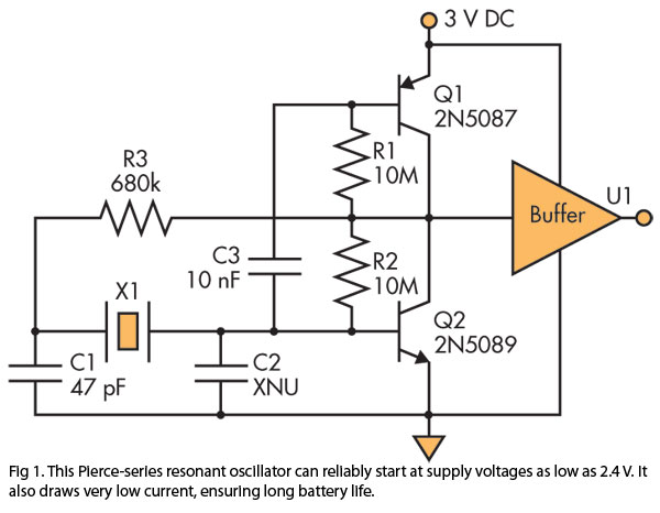
A Pierce (crystal) oscillator designed to deliver a stable clock signal for a minimum duration of one year when powered by battery voltages as low as 2.4 V. The Pierce oscillator circuit is a type of crystal oscillator that utilizes...
Our programmable MP3 player has an interface to an LCD with a HD44780 controller. These are alphanumeric LCDs with one to 4 lines of text and 16 to 40 characters per line. However, these LCDs (and LCDs in general)...
The TRF1115 is the first of two ASICs utilized in the receiver section of the Texas Instruments MMDS/MDS/WCS/802.16x chipset. This device is responsible for down-converting the input frequency to an intermediate frequency (IF) within the range of 420 MHz...
The fixed voltage power supply is useful in applications where an adjustable output is not required. This supply is simple, but very flexible as the voltage it outputs is dependent only on the regulator and transformer you choose. The...