
CO2 gas shielded arc welding power supply electromagnetic vibration circuit

The CO2 gas shielded arc welding power supply incorporates an electromagnetic vibration circuit that enhances the welding process by introducing controlled vibrations. This method is particularly beneficial in applications such as farm machinery repair, where robust and durable welds are required.
The power supply is designed to operate with a maximum arc voltage of 30V and can deliver a peak welding current of 300A, providing sufficient energy for effective welding operations. The wire feed mechanism is adjustable, allowing for a continuous speed range from 0 to 12 m/min, facilitating precise control over the material deposition rate during the welding process.
Vibration plays a crucial role in this welding technique, with a frequency set at 100 Hz and an amplitude adjustable between 0 and 0.5 mm. This controlled vibration aids in improving the quality of the weld by reducing the occurrence of defects and enhancing the penetration of the weld into the base materials.
The reactor component within the circuit features an adjustment range of 0.048 to 0.575 mH, which allows for fine-tuning of the electromagnetic properties to optimize performance based on specific welding requirements.
The circuit architecture includes a main circuit that consists of critical components such as the welding transformer (Ti) and a rectifier bridge (VDi ~ VDs), which convert the alternating current (AC) into direct current (DC) suitable for the welding process. Additionally, the control circuit is integral to the system, incorporating the main control unit, wire feed speed control, and vibration amplitude control, ensuring that all parameters can be adjusted in real-time for optimal welding conditions.
This comprehensive design of the CO2 gas shielded arc welding power supply with electromagnetic vibration capabilities makes it a versatile tool for achieving high-quality welds in demanding agricultural environments. CO2 gas shielded arc welding power supply electromagnetic vibration circuit C02 gas shielded arc welding electromagnetic vibration, vibration welding abbreviation commonly used in farm machinery repair. The maximum arc voltage of 30V, the maximum welding current is 300A, the wire feed speed is 0 ~ 12m/min (Ci stepless speed), the vibration frequency of 100 times/s, the vibration amplitude of 0-0,5 mm, reactor the adjustment range of sub-block 12, as 0.048-0, 575mH. 18 shows the circuit in Figure 9. Vibration welding power supply consists of main circuit (welding transformer Ti, rectifier bridge VDi ~ VDs, etc.), the control circuit (including the main control, wire feed speed control and vibration amplitude control circuit)
Related Circuits
This is a high quality power supply with a continuously variable stabilised output adjustable at any value between 0 and 30VDC. The circuit also incorporates an electronic output current limiter that effectively controls the output current from a few...
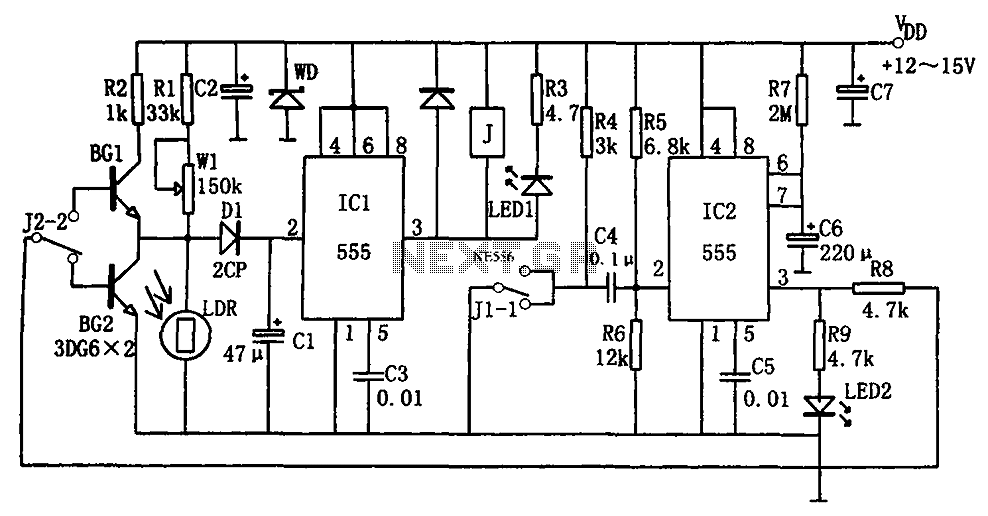
The optical control circuitry for high-performance street lighting is depicted in the figure. The circuit comprises a photoelectric conversion element, specifically a Light Dependent Resistor (LDR), a comparator circuit using an integrated circuit (IC1) which is a 555 timer,...
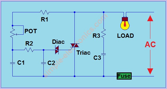
Note: Do not build or use this if you do not have any knowledge in electrical or electronics. This project is not safe for beginners, and the voltage involved is dangerous and can cause electrocution. Do not exceed the...
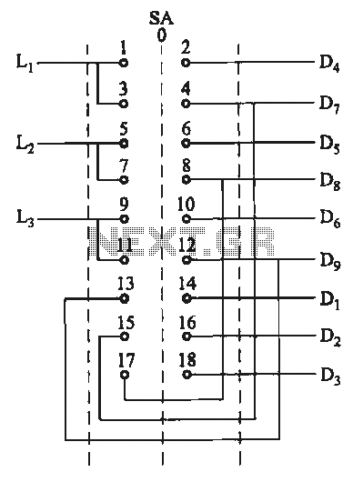
The motor switch control circuit depicted in the figure provides two speed settings for counter-steering, allowing for operation at two speeds in opposite directions. The motor switch control circuit is designed to facilitate the operation of a motor at two...
The LED current drive is regulated and programmable, which eliminates the need for current-limiting resistors. The integrated circuit (IC) features an adjustable voltage reference and an accurate ten-step voltage divider. The LED current drive circuit is designed to provide precise...
This circuit emits an intermittent beep or flashes an LED when the water level in a container reaches a predetermined height. It is designed to be mounted on top of the container, such as a plastic tank, using two...