
Code practice oscillator II

The described oscillator circuit is designed to function within a voltage range of 2 to 12 volts DC, with a specific emphasis on achieving the best audio performance between 9 to 12 volts. This voltage range is critical for ensuring that the oscillator generates a clean and robust output signal, which is essential for applications requiring high-quality audio signals and precise keying.
In this circuit, R1 plays a pivotal role in determining the frequency of oscillation. By replacing R1 with a 500K potentiometer, the user can effectively adjust the resistance, thus enabling the circuit to sweep through a wide range of audio frequencies. This feature is particularly useful in applications such as audio synthesis, where varying the frequency can produce different tones and sound effects.
The oscillator circuit typically consists of active components like operational amplifiers or transistors, which work in conjunction with passive components such as resistors and capacitors to establish the desired frequency response. The configuration may include feedback loops that stabilize the oscillation and maintain consistent output levels.
To optimize performance, it is recommended to select high-quality components that can handle the specified voltage range and provide minimal distortion. Additionally, proper layout and grounding techniques should be employed to minimize noise and enhance the overall performance of the oscillator circuit.
This oscillator design is versatile and can be applied in various electronic projects, including signal generation, sound synthesis, and modulation applications. Adjusting the frequency range via the potentiometer allows for creative exploration within the audio spectrum, making it a valuable tool for engineers and hobbyists alike.Oscillator, works with2 to 12Tdc (but 9 to 12 volts gives best volume and clean keying) R1 can be replaced with a 500K pot and the circuit will sweep the entire audio frequency.
Related Circuits
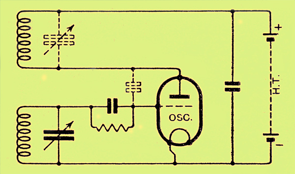
The congestion of the ether is increasing, prompting ongoing efforts to extend communication channels to higher frequencies. Wavelengths as short as 12 meters are now common, but operating below this presents significant challenges. At approximately one meter, the oscillation...
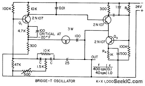
This circuit incorporates heavy degenerative feedback, utilizing a small lamp as a nonlinear compensating resistance. It provides a constant output frequency and voltage for supply voltages ranging from 12 to 32 V, and operates effectively at temperatures as low...
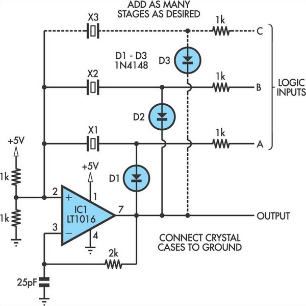
This oscillator circuit allows crystals to be electronically switched through logic commands. The circuit is best comprehended by initially disregarding all crystal components. The oscillator circuit described functions as a frequency generator that utilizes the properties of quartz crystals to...
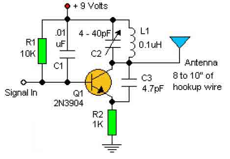
This basic RF oscillator circuit is easy to build and the components are not critical. Most of them can be found in your junk parts box. The L1 antenna coil can be made by close winding 8 to 10...
An oscillator is a circuit that generates a frequency source such as a sine wave, square wave, or pulse train. It combines a frequency-sensitive circuit, like an LC circuit or a crystal, with a negative resistance typically provided by...
This simple and inexpensive crystal oscillator consists of one-third of a 7404 hex inverter, four resistors, and a crystal. The inverters are biased into their linear regions by resistors R1 to R4, while the crystal provides the necessary feedback....