
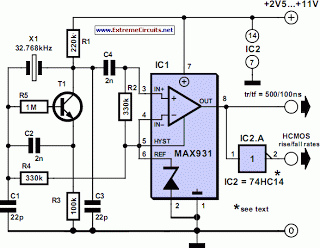
Switchable Output Crystal Oscillator

The oscillator circuit described functions as a frequency generator that utilizes the properties of quartz crystals to produce stable oscillations. It operates by enabling the electronic switching of these crystals based on logic commands, which can be provided by microcontrollers or other digital logic devices.
At its core, the circuit typically includes a crystal oscillator configuration, which consists of an active component such as a transistor or an operational amplifier, and passive components including resistors and capacitors. The crystal itself serves as a frequency-determining element, providing high stability and precision in the output frequency.
In operation, when a logic high signal is applied to the control input, the circuit activates the oscillator, allowing the crystal to resonate and produce an output signal at its fundamental frequency. Conversely, when the logic signal is low, the oscillator is disabled, effectively turning off the output. This switching capability makes the circuit suitable for applications where precise timing or frequency generation is required, such as in communication systems, clock generation, or signal processing.
The design of the circuit can be enhanced by including additional features such as feedback mechanisms to stabilize the output frequency further or using multiple crystals to allow for different output frequencies based on the logic commands received. The incorporation of filtering components can also improve the signal quality by reducing unwanted harmonics and noise.
Overall, this oscillator circuit represents a versatile solution for integrating crystal-based frequency generation into digital systems, providing both flexibility and reliability in various electronic applications.This oscillator circuit permits crystals to be electronically switched by logic commands. The circuit is best understood by initially ignoring all crystal.. 🔗 External reference
Related Circuits
The 32-kHz low-power clock oscillator provides several advantages compared to traditional oscillator circuits that utilize a CMOS inverter. These inverter circuits often exhibit issues such as significant fluctuations in supply currents across a 3V to 6V supply range, making...
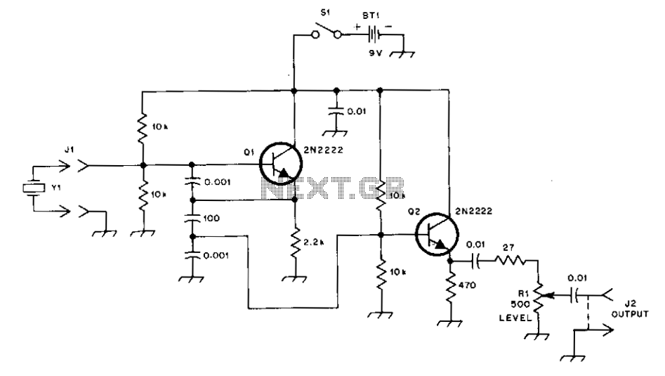
This general-purpose signal source is highly effective for signal-tracing applications. The output level is adjustable, exceeding 1 Vrms into a 50 Ω load. It is compatible with nearly any crystal in the 1 to 15 MHz frequency range. Q1...
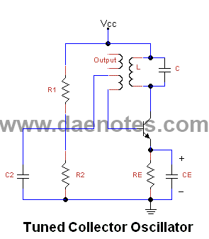
These are resonant circuits or tank circuit oscillators. They are commonly used to produce high frequencies ranging from 1 MHz to 500 MHz; hence, they are also known as RF oscillators. These oscillators are utilized in RF generators, radio...
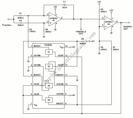
This is a schematic diagram of a micropower voltage-controlled oscillator circuit. This circuit can generate square and triangle wave outputs and only requires minimal power. The micropower voltage-controlled oscillator (VCO) circuit is designed to produce both square and triangle waveforms,...
This application note describes a digital blood pressure meter concept that utilizes integrated pressure sensor analog signal-conditioning circuitry, microcontroller hardware/software, and a liquid crystal display. The sensing system measures cuff pressure (CP) and extracts pulses for analysis to determine...
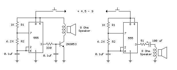
The following circuit is a basic 555 square wave oscillator. Features include a 1 kHz tone, simple circuitry, a current limit of 200 mA, reduced inductive voltage, and a supply voltage range of 4.5 to 9 volts. Components used...