
Cold cathode fluorescent lamp CCFL power supply

The CCFL drive circuit typically consists of a high-frequency oscillator, a transformer, and a control mechanism for adjusting the output voltage. The oscillator generates a high-voltage sine wave, which is then stepped up by the transformer to the required voltage level for the CCFL. The transformer is designed to handle high-frequency signals and must be rated for the power requirements of the CCFL.
To enable smooth dimming, a pulse-width modulation (PWM) technique is often employed. This involves varying the duty cycle of the high-frequency signal, effectively controlling the average power delivered to the CCFL. This method allows for fine adjustments in brightness without flickering, providing a stable light output across the full intensity range.
For measuring the output voltage and waveform, the circuit requires specialized high-voltage probes. The Tektronix P-6009, P6013A, and P6015 probes are designed for high-voltage applications and can safely measure the output without risk of breakdown. Standard oscilloscope probes are not suitable for this application due to their lower voltage ratings, which could lead to failure or inaccurate readings.
In summary, the CCFL drive circuit is an essential component for backlighting LCD displays, providing both the necessary high-voltage drive and the capability for adjustable brightness. Proper measurement techniques and equipment are critical for ensuring safe and accurate performance of the circuit.CCFLs are often used to backlight the LCD displays of portable computers Such lamps require a high-voltage sine-wave drive. This circuit provides such drive and permits lamp intensity to be varied continuously and smoothly from zero to full intensity.
Notice that a Tektronix probe type P-6009 acceptable ‰or types P6013A and P6015 preferr ed ‰probes must be used to read the L1 output The vast majority of oscilloscope probes will break down if used for this measurement unless the probes are rated for wideband high voltage 🔗 External reference
Related Circuits
This circuit employs an 87C57 microcontroller along with several peripherals to convert X-10 power-line carrier-code formats from a personal computer for use with an X-10 power-line interface in a home-control system. Software details can be found in the reference. The...
A high voltage switching stabilized voltage supply circuit is illustrated in the diagram. This is the switching power supply for an 80P type color television. It utilizes auto-excitation and a PWM circuit. The output is isolated from the power...
The purpose of a DC power supply is to deliver the necessary level of DC power to a load by utilizing an AC supply at the input. Various applications demand different specifications; however, contemporary DC power supplies often ensure...
This inverter is designed to operate fluorescent lamps ranging from 8W to 20W, with optimal performance achieved using 16W tubes. It preheats the electrodes and maintains their temperature during operation. The inverter functions by converting direct current (DC) into alternating...
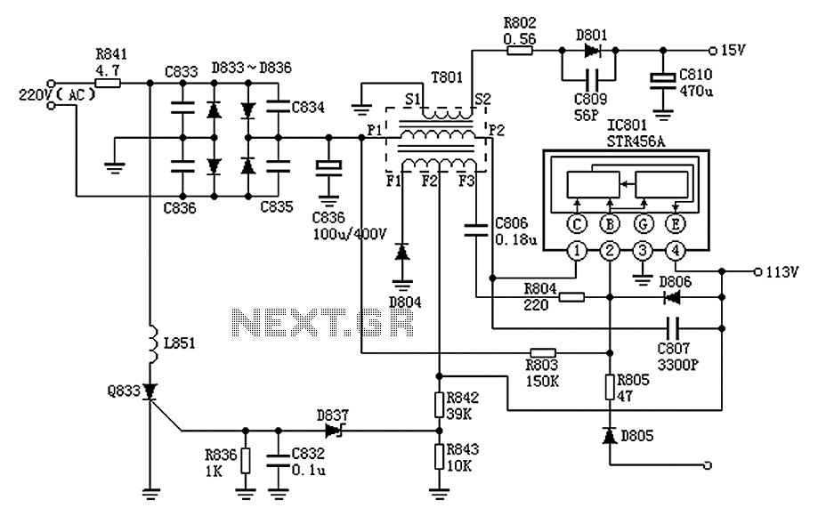
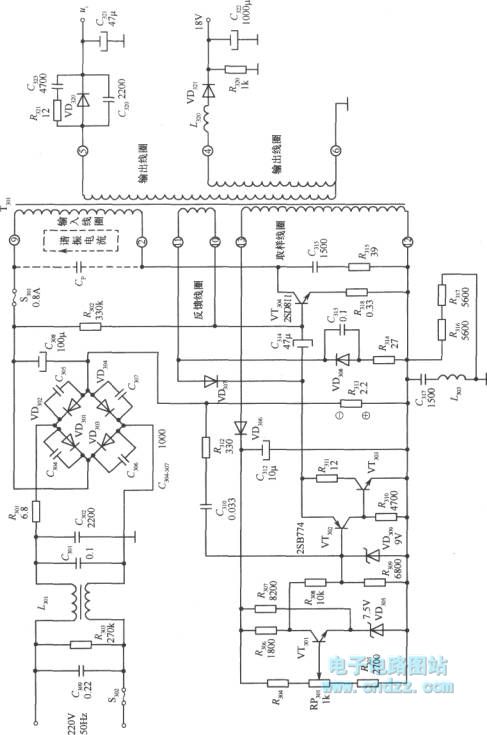
The Panasonic M12H switching power supply circuit is utilized in Panasonic models such as TC-230H, TC-2030DHN, TC-830D, and TC-840D. The circuit operates with an oscillation frequency that generates approximately 300V DC voltage at C836. The T801 transformer is involved...
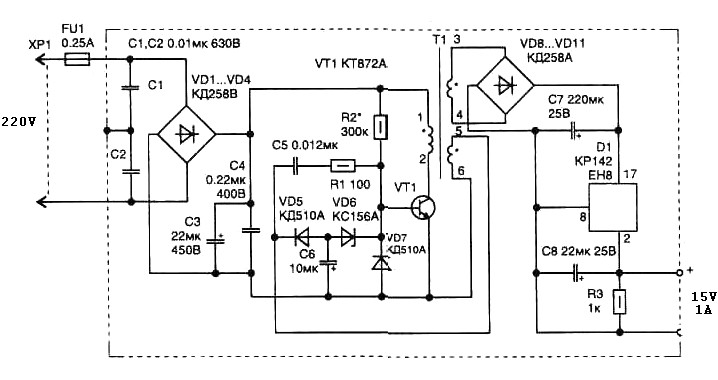
A 15 Watt switching power supply schematic diagram features a pulse transformer T1 constructed on a ferrite core M2500NMS-2 or M2000NM9, with a Sh5h5 size (cross-section of the magnetic coils at the location of 5G—5 mm with a gap...