
Cold Sensor

The described component exhibits a negative temperature coefficient, which means that its resistance decreases as ambient temperature increases. This behavior is characteristic of certain thermistors, specifically NTC (Negative Temperature Coefficient) thermistors, which are commonly used in temperature sensing and compensation applications.
In a circuit design, this NTC thermistor can be integrated with various components such as LEDs, buzzers, transistors, and capacitors to create a temperature-sensitive device. For instance, when the temperature rises, the resistance of the thermistor drops, allowing more current to flow through the circuit. This increased current can be utilized to activate an LED, providing a visual indication of temperature changes, or to trigger a buzzer, which can serve as an audible alarm.
The transistor can be employed as a switch or amplifier in this configuration. When the thermistor's resistance decreases sufficiently, it can turn on the transistor, which in turn allows a larger current to flow through the LED or buzzer. The capacitor can be used for smoothing out voltage fluctuations in the circuit, ensuring stable operation.
In summary, the integration of an NTC thermistor with these components allows for the development of a versatile temperature monitoring and alert system that can be applied in various electronic applications, including HVAC systems, automotive temperature sensing, and consumer electronics.Its resistance decreases when the temperature in its vicinity increases above one degree or more. Component: LED, Buzzer, Transistor, Capacitor, .. 🔗 External reference
Related Circuits
The purpose of this circuit is to animate shop windows using a capacitive sensor placed behind a postcard-like banner. The card is positioned against the glass inside the shop window, allowing visitors to activate the relay by placing their...
A PIR sensor is triggered when using a timer to wait for 2 seconds after the sensor is activated. Without the timer, the sensor operates as intended. The PIR sensor is connected to an ATMega328p microcontroller, which has three...
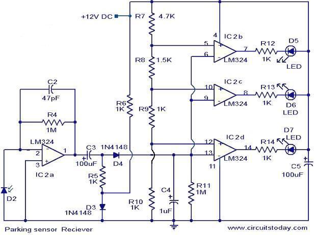
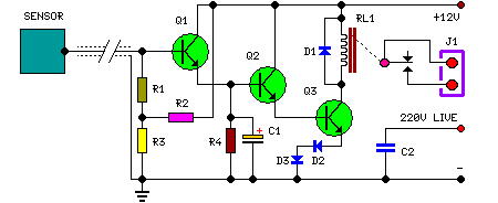
The following circuit illustrates the use of the LM324 in a parking sensor circuit diagram. Features: When the obstacle is beyond 25 cm, none of the above LEDs will activate. The LM324 is a quad operational amplifier that is commonly...

Laser-receiver circuits must bias their avalanche photodiodes (APD) to achieve optimal gain. Unfortunately, an APD's gain depends on the operating temperature. The circuit controls the operating voltage of an APD over a large temperature range to maintain the gain...
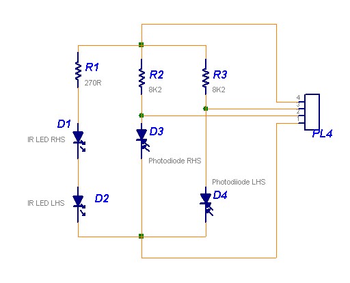
The following circuit illustrates a Line Follower Sensor Circuit Diagram. Features include a simple design, with Infrared LEDs D1 and D2 emitting infrared light. The Line Follower Sensor Circuit is designed to detect the presence of a line, typically a...

In the present day, a wide variety of sensors are available to measure almost anything. This tutorial will explore the fascinating world of sensors, starting with a very simple analog temperature sensor, the LM35. The process of interfacing it...