
Line Follower Sensor

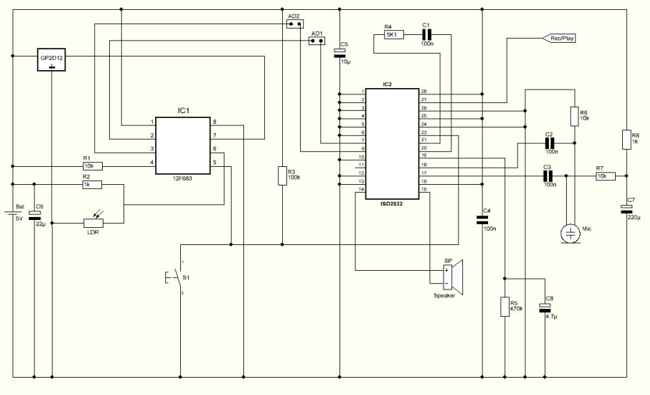
The Line Follower Sensor Circuit is designed to detect the presence of a line, typically a black line on a white surface, allowing a robot or vehicle to follow the path. The core components of this circuit include two Infrared LEDs (D1 and D2) and phototransistors or photodiodes that act as sensors.
When the Infrared LEDs emit light, it reflects off the surface beneath them. If the surface is light-colored (like white), the light is reflected back to the phototransistors, which will not trigger the sensors. Conversely, if the surface is dark (like black), less infrared light is reflected, leading to a different response from the sensors. This contrast allows the circuit to determine the position of the line.
The circuit typically includes a microcontroller or an operational amplifier to process the signals received from the phototransistors. Based on the input from the sensors, the microcontroller can adjust the motion of the motors controlling the wheels of the robot, ensuring that it stays on the designated path.
Powering the circuit can be achieved using a battery or a power supply, ensuring that the LEDs and sensors receive the necessary voltage and current for operation. The simplicity of this circuit makes it an excellent choice for educational purposes, as well as for hobbyists interested in robotics.
Overall, the Line Follower Sensor Circuit exemplifies a fundamental application of infrared technology in automation and robotics, demonstrating how basic electronic components can be used to create intelligent behavior in machines.The following circuit shows about Line Follower Sensor Circuit Diagram. Features:Simple circuit, Infra-Red LEDs D1 and D2 will emit Infra-Red .. 🔗 External reference
Related Circuits
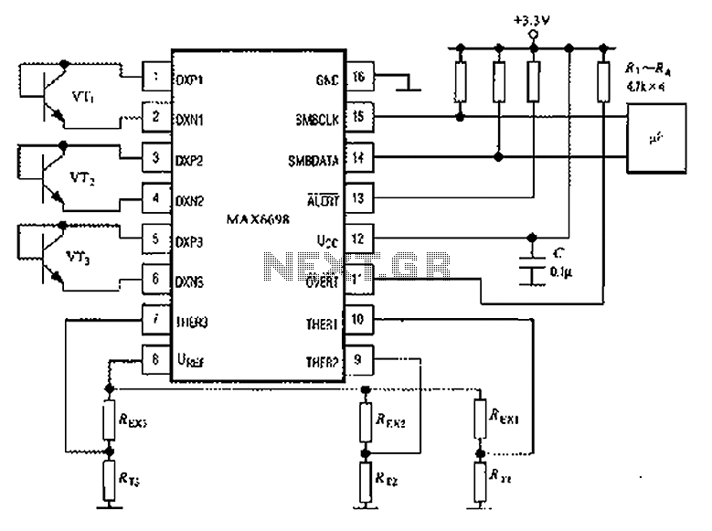
The circuit illustrated in the figure involves the MAX6698 maximum temperature sensor, which utilizes three transistors (VT1 to VT3) and three thermistors (RT1 to RT3). An internal reference voltage source is connected through resistors UREF REX1 to REX3, providing...
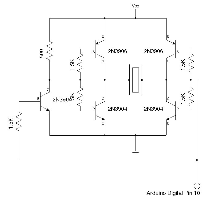
Some ultrasonic range finders for a project. Most commercial sensors like Parallax's PING sensor and similar products are quite expensive, especially when multiple units are needed. Therefore, a decision was made to build the sensor independently. The theory behind...
The use of a quarter-wave parallel-wire line as a tuning unit has been discussed in the chapter on Short-Lines, where it was pointed out that these circuits have comparatively high Q even at higher frequencies. Their significant length (approximately...
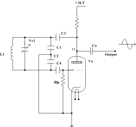
A valve radio receiver, in its simplest form, consists of a frequency-determining tuned circuit made up of an inductor and capacitor in parallel, followed by a series of valves connected together. These valves amplify the signal, perform detection (rectification),...
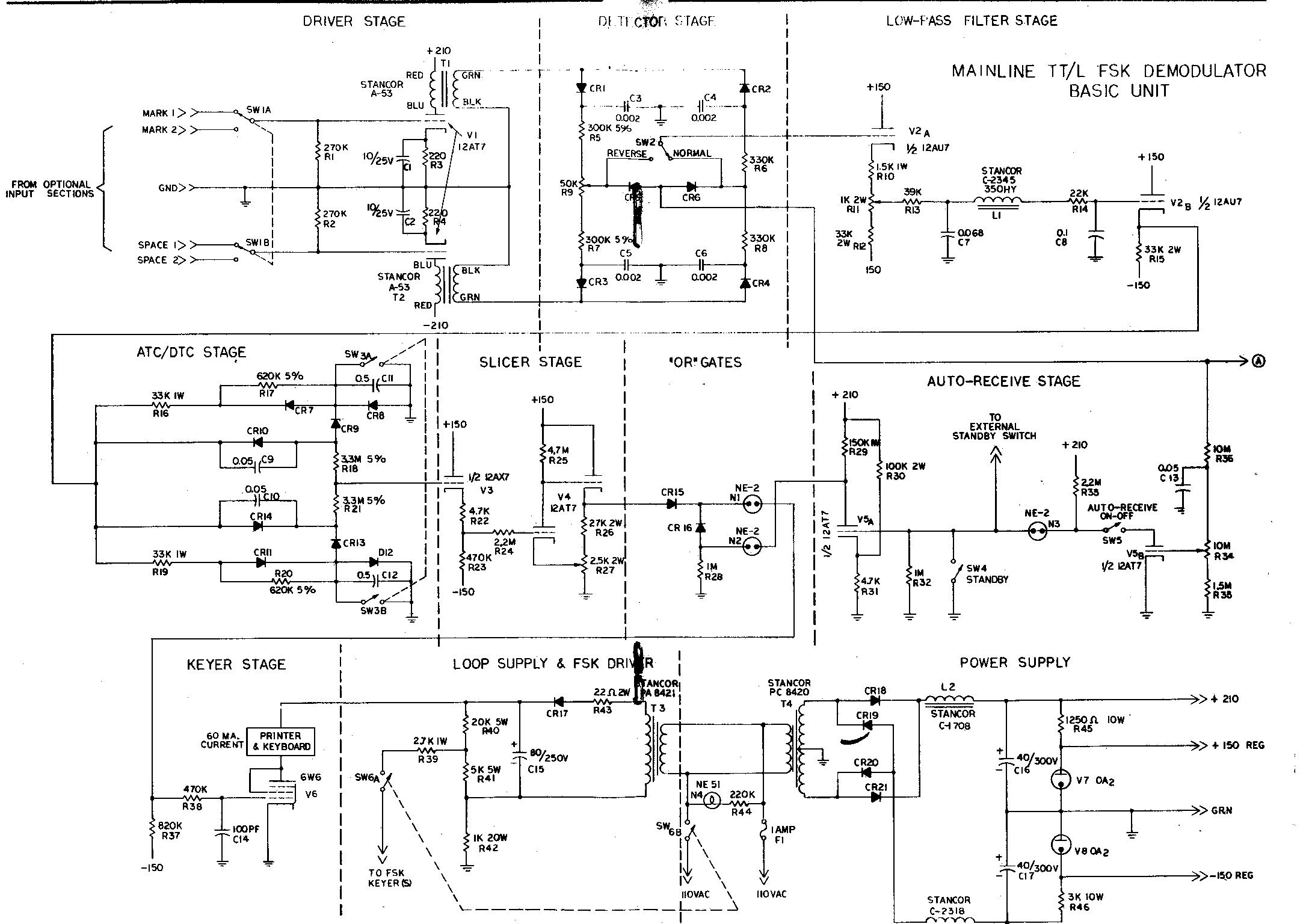
The term "demodulator" is becoming a standard in both commercial and military sectors. "Converters" are often associated with devices that automatically transform Morse code into RTTY, convert 8-level signals to 5-level, or adjust baud rates from 50 to 45,...
Halloween is coming up and it's time to do some pranks. Everyone likes Halloween and I'm no exception. Every year me and my wife decorate the house with lots of bugs, spider webs, creepy posters and of course lots...