
Diode Sensor For Lasers

The laser-receiver circuit described is designed to optimize the performance of avalanche photodiodes (APDs) across a wide temperature range, addressing a critical aspect of photodiode operation: gain stability. The circuit employs a temperature sensor, D1, which is thermally coupled to the APD, ensuring that the temperature variations affecting the APD's gain are accurately monitored.
A voltage regulator, designated as IC1, provides a stable reference voltage essential for consistent operation. The circuit features a constant current biasing arrangement for the temperature sensor, implemented through IC2A and transistor Q1. This biasing is crucial for maintaining the accuracy and reliability of the temperature readings.
To manage the gain adjustments, the circuit includes multiple amplification stages (IC2B, IC2C, IC3A/IC3B, and IC3C), which take the varying voltage output from D1 and amplify it accordingly. This amplified signal is then used to adjust the biasing of Q2, ensuring that the APD operates at its optimal gain level, which is particularly important as the APD's performance can significantly degrade if not properly biased.
The design incorporates potentiometer R1, allowing for manual adjustment of the amplification factor within a specified range of 5 to 15. This feature provides flexibility in tuning the circuit to achieve the desired performance characteristics based on specific application requirements. Additionally, resistor R2 is employed to set the appropriate voltage level corresponding to the optimal gain of the APD at a nominal temperature of 22°C, which is critical for achieving the best performance from the specific type of APD being utilized.
The circuit has been rigorously tested with an RCA C 30954E APD, demonstrating its capability to maintain stable gain across a temperature range of -40 to +70°C. During testing, the semiconductor laser's radiation was effectively transmitted onto the APD's active surface via fiber optic cable, allowing for real-world evaluation of the circuit's performance. The results indicated that the gain remained remarkably stable, varying by no more than ±0.2 dB throughout the entire temperature range, showcasing the effectiveness of the design in maintaining optimal APD operation under varying environmental conditions. Laser-receiver circuits must bias their avalanche photo diodes (APD) to achieve optimal gain. Unfortunately, an APD "s gain depends on the operating temperature. The circuit controls the operating voltage of an APD over a large temperature range to maintain the gain at the optimal value. The circuit uses Dl as a temperature sensor, thermally matched with the APD. A voltage regulator, IC1, supplies the necessary reference voltage to the circuit. IC2A and Ql bias Dl at a constant current. IC2B, IC2C, IC3A/IC3B, and IC3C amplify Dl"s varying voltage and set Q2 to the optimal-gain corresponding value.
Potentiometer Rl controls the amplification over a range of 5 to 15. R2 controls the voltage level, which corresponds to the optimal gain of the APD at 22°C (the temperature is specific to the type of APD). The circuit shown was tested with an RCA C 30954E APD. The tests covered -40 to + 70°C and used a semiconductor laser. The laser radiation was transmuted on the APD"s active surface in the climatic room via fiberoptic cable.
The gain varied by, at most, ±0.2 dB over the entire temperature range. 🔗 External reference
Related Circuits
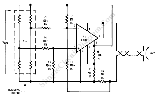
Bridged resistive sensing elements are commonly used in resistive type sensors and transducers. This type of sensor requires a biasing voltage to operate. The LM10 provides low... Bridged resistive sensing elements are integral components in various resistive sensors and transducers,...
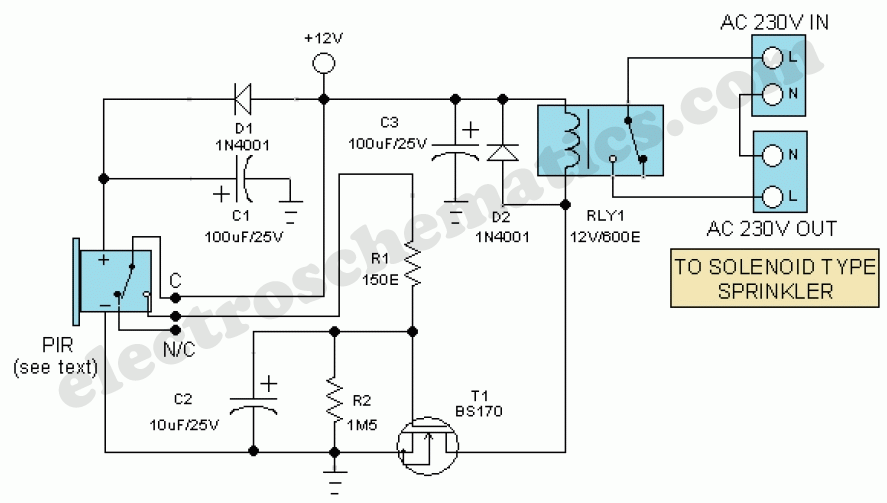
Install the PIR module hanging from a 3-meter high mast to cover a 10-meter radius area. Connect its supply and relay terminals to the finished and enclosed circuit, ensuring the correct polarity is observed. A 4-core screened cable can...
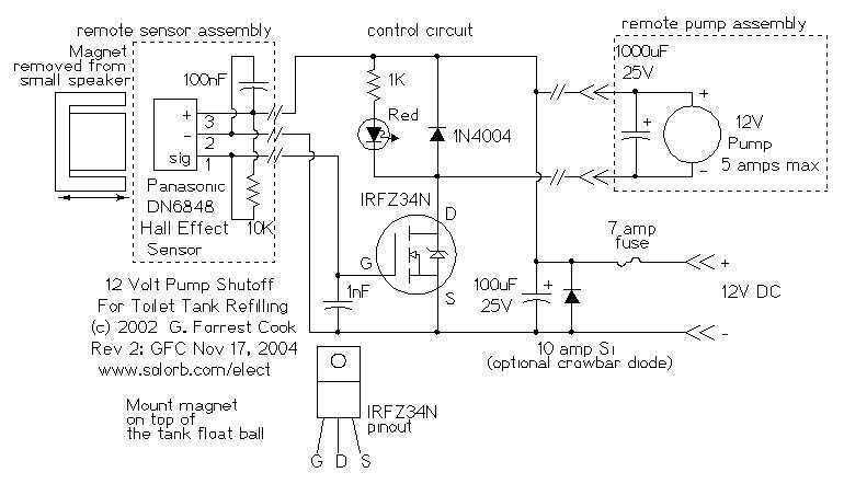
The 12 Volt power in my application comes from a small solar power system; it may also be provided by a suitable wall-wart DC power supply. The cistern is located below the toilet tank; the pump moves the water...

The circuit is designed to sense ambient light levels and activate lights when it is dark. A prototype was successfully built on a breadboard using an LM324 comparator, various resistors, a trimmer resistor, and a photocell. Subsequently, a PCB...

Detecting the color of an object can be an interesting and useful electronic application. This can be achieved using a color sensor like the TCS3200 in conjunction with a general-purpose microcontroller such as the AVR ATmega32. The TCS3200 chip...
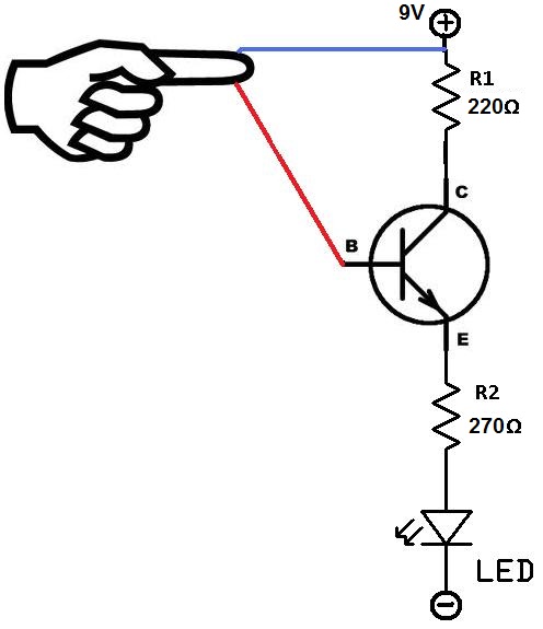
This project utilizes two wires, one red and one blue, which function as touch sensor wires. When a person touches both wires, the circuit closes, allowing current to flow and illuminate the LED. A 9-volt battery or an external...