
Color TV Camera Tutorial - Block Diagrams

The Colour TV Camera tutorial encompasses various aspects of electronic circuit design, particularly focusing on block diagrams that illustrate the fundamental operation of a color television camera system. The modulation technique is crucial in this context, as it facilitates the transmission of audio signals over considerable distances.
In a typical color TV camera, the system can be divided into several functional blocks: the lens system, image sensor, signal processing unit, modulation circuit, and transmission module. The lens system captures the light from the scene and focuses it onto the image sensor, which converts the optical signals into electrical signals.
The image sensor typically consists of a charge-coupled device (CCD) or a complementary metal-oxide-semiconductor (CMOS) sensor, which is responsible for converting the light intensity into voltage levels corresponding to the brightness of the image. The output from the image sensor is a series of analog signals that represent the captured image.
Following this, the signal processing unit enhances and prepares these signals for modulation. This unit may include amplifiers, filters, and analog-to-digital converters (ADCs) to improve signal quality and convert the analog signals into a digital format for further processing.
The modulation circuit then takes the processed audio and video signals and combines them with a high-frequency carrier wave. This is performed using techniques such as amplitude modulation (AM) or frequency modulation (FM), where the low-frequency audio signal is superimposed onto the carrier wave. The modulation process is essential for enabling the transmission of audio signals alongside video signals, ensuring that both can be sent over the same medium without interference.
Finally, the transmission module broadcasts the modulated signals over the airwaves, allowing them to be received by compatible television sets. The receiving end demodulates the signals, extracting the audio and video components for display.
This comprehensive understanding of the color TV camera system and its modulation process is vital for hobbyists and professionals engaged in electronics projects and telecommunications. The block diagrams serve as an effective visual aid, simplifying the complex interactions between the various components involved in the operation of color TV cameras.Colour TV Camera Tutorial - Block Diagrams - Electronics Circuit and Tutorials - Hobby Science Projects - Modulation enables low frequency audio signals to be radiated long distances. This is done by superimposing the low frequency audio signal on the high frequency carrier wave by the process of modulation
🔗 External reference
Related Circuits
The microphone amplifier/modulator is built around the LM324, which is a quad operational amplifier that provides sufficient quality amplification for the voice captured by the condenser microphone. The LM324 is a versatile quad op-amp that consists of four independent, high-gain,...
It is necessary to adjust the 10K potentiometer while aiming the device at the television to obstruct the infrared rays from the remote control. This adjustment can be achieved through a process of trial and error. The circuit in question...
Do not forget to seal your wire splices with heat shrink tubing. It provides tensile strength to wires, is flame-retardant, and protects against fraying. Heat shrink tubing forms a protective, insulated, water-resistant covering over wiring splices, crimp terminals, and...
The image below depicts a block diagram of a complete mixer that consists of four input amplifier modules followed by four switchable tone management modules, one stereo line input, four mono main faders, one stereo dual-ganged main fader, four...
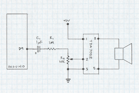
This document demonstrates the use of an Arduino PWM output pin to generate sound. The output pin can be toggled rapidly between LOW and HIGH states to create a square wave. If the frequency of this square wave is...
The concept of a color organ involves the transformation of sound, including musical tones, into light. According to wave theory, both music and light possess similar wave characteristics. A color organ is an electronic device that visually represents sound through...