
PWM sound Tutorial

The circuit described utilizes an Arduino microcontroller to generate sound through Pulse Width Modulation (PWM). The PWM output pin from the Arduino is programmed to switch rapidly between LOW and HIGH states, producing a square wave signal. The frequency of this square wave can be adjusted within the audible range of 20 Hz to 20 kHz, allowing for the generation of various tones.
In the first output scheme, the Piezo Speaker is directly connected to the PWM pin. This configuration is simple and effective for generating basic tones, although the sound quality and frequency response will depend on the specifications of the Piezo Speaker used.
The second method introduces a low-pass filter, which is essential for transforming the square wave into a smoother line-level audio signal. This filter typically consists of resistors and capacitors that attenuate the higher frequency components of the square wave, resulting in a more sinusoidal waveform. This output can then be connected to standard audio equipment, such as amplifiers or mixers, allowing for broader applications in audio projects.
The third scheme incorporates a TDA7052 audio amplifier, which is designed for low-power audio amplification. The TDA7052 chip is connected to the output of the low-pass filter and features built-in volume control. This setup allows for the amplification of the audio signal to drive a small 8-ohm speaker, providing a more robust sound output suitable for various applications. The combination of the Arduino, low-pass filter, and TDA7052 amplifier creates a versatile audio generation system that can be tailored to different sound requirements.Here we demonstrate the use of an Arduino PWM output pin to generate sound. The output pin can be toggled very quickly from LOW to HIGH generating a square wave. If the frequency of this square wave is within the range of 20-20, 00Hz and sent directly into a Piezo Speaker, an audible tone will be produced (in reality, the range of output is limited by the specs of the speaker and does not cover the entire audible frequency range. ) This tutorial covers three sound output schemes: first is the method with the Piezo Speaker connected directly to the Arduino output pin. The second uses a low pass filter to transform the square wave to a line level signal that can be used with standard audio equipment.
The third output scheme uses a TDA7052 amplifier (8-DIP) chip with volume control and sends the audio signal into a small 8 OHM speaker. 🔗 External reference
Related Circuits
This controller is designed primarily for controlling model trains and can deliver approximately 12-15 Volts, though it operates effectively at voltages as low as 3V, including a 6V supply for certain accessories. The maximum output current is theoretically around...
The circuit is fundamentally based on a well-tested simple microphone preamplifier design. A prototype of this circuit has been constructed and has demonstrated effective performance. The Sound Blaster soundcard series (SB16, SB32, AWE32, and AWE64) features a microphone input...
A constant speed motor control can be achieved using closed-loop (servo) control. A constant speed motor maintains a steady speed regardless of variations in load. In a closed-loop control system, feedback is utilized to compare the actual speed of the...
Utilizing an analog audio line delay, it is possible to virtually adjust the size of a room. By simply turning a knob on the audio equipment, one can modify the perceived room size. The circuit described herein facilitates this...
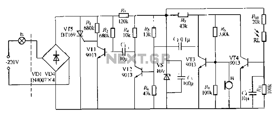
This circuit describes a sound and light control delay system for a walkway stairs light switch. It involves various components including 220V AC electric bulbs, diodes (VD1-VD4), and resistors. The circuit utilizes a rectifier regulator to stabilize the voltage...
PWM waveforms are widely utilized to regulate the speed of DC motors. The duty cycle of the digital waveform can be established either through an adjustable analog voltage level (as seen in a NE555-based PWM generator) or through digital...