
colours sensor detector circuit

The color detection circuit utilizes a combination of photodetectors and microcontrollers to accurately identify and differentiate between various colors. The primary colors are detected using RGB (Red, Green, Blue) sensors, which measure the intensity of light in each of these three wavelengths. The readings from these sensors are then processed to determine the presence of primary and secondary colors based on predefined thresholds.
For detecting black and white, the circuit employs a light intensity measurement that assesses the overall brightness of the object. When the intensity is low, the object is classified as black, while a high intensity indicates the presence of white. The circuit's design incorporates analog-to-digital converters (ADCs) to convert the analog signals from the sensors into digital data that can be processed by the microcontroller.
The microcontroller is programmed with an algorithm that compares the sensor readings against a color lookup table, enabling real-time color recognition. This allows the system to output the detected color through a display or interface, providing immediate feedback.
In terms of hardware, the circuit may include additional components such as resistors, capacitors, and LEDs for status indication. Proper calibration of the sensors is essential to ensure accuracy and reliability in various lighting conditions. Overall, this color sensing circuit serves applications in robotics, automation, and interactive systems, where color recognition is crucial for functionality.This circuit can sense eight colours, i. e. blue, green and red (primary colours); magenta, yellow and cyan (secondary colours); and black and white. The circuit is based on the fundamentals of optics and digital electronics. The object whose colour is required to be detected should be placed in front of the system. 🔗 External reference
Related Circuits

Below is the schematic diagram of an audio input module. This module is capable of producing a DC output voltage that is proportional to the amplitude of the input signal. The audio input module typically consists of several key components...

Driving a series of white LEDs allows for a consistent current to flow through each LED, resulting in uniform brightness. However, a disadvantage of this series configuration is that the driving voltage must account for the forward voltage drop...

A neon bulb and a CdS photocell are enclosed in a light-tight enclosure to form an optocoupler. A diac/triac combination is employed to create a snap-switch effect. A second CdS photocell serves as the primary sensor. As darkness approaches,...
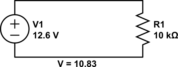
Connect a 12V fan to this circuit that consumes 70mA (0.07A), ensuring the circuit can supply at least that amount of current. There appears to be a misunderstanding regarding the analysis. The voltage drop across the resistor equals the...
This emergency LED light is simple, inexpensive, and easy to build. The circuit connects to the battery, activating when the main power source is unavailable, such as during brownouts. White LEDs turn on automatically. Initially, the output voltage from...

The DK-5A, 5D, and SDb control boxes are equipped with a thermal electromagnetic overcurrent release, as depicted in Figure 6-80. The trip mechanism provides both overload and instantaneous short circuit protection with a long delay feature. In the figure,...