
LED Colour Organ circuit

The TOMTE circuit exemplifies a well-thought-out design for a sound-to-light interface, integrating various components to create a seamless audio processing experience. The choice of a digital potentiometer allows for precise gain adjustments, enabling the microcontroller to dynamically adapt to varying sound levels and maintain optimal performance. The use of the LM386 audio amplifier ensures efficient amplification of the audio signal while minimizing power consumption, which is particularly advantageous in applications where power availability is limited.
The frequency filtering aspect of the circuit is critical, as it allows the system to respond to specific audio frequencies, enhancing the visual effects produced by the LED lights. By segmenting the audio signal into low, mid, and high-frequency ranges, the circuit can activate different sets of lights based on the characteristics of the incoming sound. This not only adds a layer of complexity to the visual output but also creates a more engaging experience for the viewer.
The implementation of peak detectors is another significant feature, as these components convert the fluctuating AC audio signals into steady DC levels that can be easily interpreted by the PIC microcontroller. This conversion is pivotal for accurate measurement and control of the lighting effects, ensuring that the LED lights respond appropriately to the audio input.
In summary, the TOMTE project represents a comprehensive approach to creating an interactive light display that responds to sound. The thoughtful integration of components, including the microphone pre-amplifier, digital potentiometer, and audio amplifier, culminates in a robust design that can serve as a foundation for various audio-visual projects beyond the holiday season. The flexibility and adaptability of the circuit make it an excellent reference for engineers and hobbyists looking to explore sound-reactive lighting systems.Nearly all the existing designs I found used direct switching of the lights (with no software control in between) and contained manual potentiometers for light sensitivity and overall gain setting. Furthermore, I couldn`t find many references to the frequency filter circuitry explaining the frequencies the circuit was designed to detect and why (it seems most published designs are based on other published designs leading
to fairly `sloppy` audio-stage circuitry). So it was time to brush up on op-amp filter design and build something myself. At the local hardware store I found some strings of LED lights (for Christmas decorations) and thought that wiring up a Christmas tree as a colour organ would be a pretty fun thing to do. From that T. O. M. T. E. was born (Tone Operated Microprocessor Tree Enhancement), details of which you can find below along with detailed construction notes.
(for the non-Swedish reader, Jultomte is Swedish for Santa Claus, hence the funky abbreviation!) The sound processing circuitry for TOMTE is probably a little over-the-top for the application it is used for here, however it represents a good quality sound-to-light interface design which is probably useful for a number of other light/audio projects I can think of, so even if you don`t intend to build the Xmas decoration I designed, the circuitry is still useful. The microphone is connected to a pre-amplifier (because microphones produce so little electricity) and then on to an amplifier (which has automatic gain control from the microcontroller), the signal is then split into 3 frequency ranges (low, mid, high).
Finally the sound is passed through peak-detectors (actually these add a little gain and convert the AC audio signal into DC) which is then measured using the ADC of a PIC18F. The PIC MCU then controls the available lights and the gain of the amplification block (which is why there is also an unfiltered audio feed to the PIC for `listening` to the overall gain).
The microphone pre-amplifier is a simple electret microphone amplifier which uses a single op-amp from the LM324 quad op-amp IC. This circuit provides a moderate amount of fixed gain to the microphone signal to allow the later stages to function even with a relatively quiet music source.
Since electrical noise and power-line jitter is critical in this stage large decoupling capacitors are used to remove as much noise as possible so that interference isn`t introduced at the primary audio stage. The advantage of a separate pre-amp is that you can easily modify the circuit to run from a standard audio line-in by bypassing the pre-amp and wiring the line-in directly to the amplifier.
If you use a `switched` socket you can even make the line-in jack disconnect the microphone when plugged in and therefore make the unit run from either source. The amplifier consists of two ICs; firstly the output from the pre-amplifier is passed through a Microchip MCP41010 10K digital potentiometer (with SPI serial interface) which allows the microcontroller to change the input gain from the pre-amplifier to the amplifier.
The amplification is performed by a LM386 low-power audio amplifier which I chose because of its simple design and the fact it runs happily from a single 5V supply. The LM386 can provide up to 200x gain (by placing a capacitor/resistor combination between pins 1 and 8) but in the TOMTE circuit it provides 20x gain which was enough to get a `loud` signal without any clipping even at moderately low sound-levels to the microphone.
The filter design was one of the most c 🔗 External reference
Related Circuits
The system primarily consists of a permanent magnet disk, an integrated Hall sensor, a strobe gate, time base signal circuits, a power counting circuit, and a digital display circuit. The counting and digital display circuit utilizes the CMOS-LED digital...
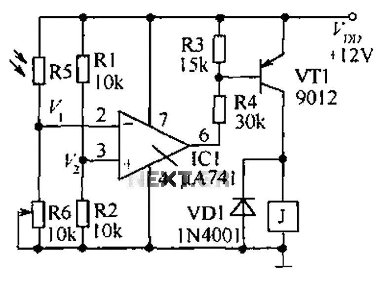
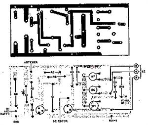
The circuit functions as a precision bright light control circuit, operating independently of variations in power supply voltage and ambient temperature. Resistors R1, R2, R6, and the photosensitive resistor R5 form a two-arm Wheatstone bridge. The precision bright light control...
In certain industries, a computer-controlled 4-20 mA current loop is utilized to manage various equipment. This current loop is employed to transmit a signal over a distance. The 4-20 mA current loop is a standard method for transmitting analog signals...

This DC negative-voltage generator based on the 555 produces a negative output voltage equal to approximately 2 times the DC supply voltage. The described circuit utilizes the popular 555 timer IC configured in an astable or monostable mode to generate...
This simple stereo encoder circuit schematic is built with two ICs, MMC4066E and MMC4047, along with one transistor, BC547B. The audio output is taken from pins 2 and 3 of IC1. The stereo encoder circuit utilizes the MMC4066E, which is...
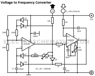
This voltage-to-frequency converter circuit features a voltage-controlled oscillator with a small deviation of 0.5%. The integrated circuit IC1 operates as a multivibrator. The voltage-to-frequency converter circuit is designed to convert an input voltage into a corresponding frequency output. The core...