
COLPITTS 1 To 20 MHz Crystal Oscillator

The Colpitts oscillator is a type of electronic oscillator that uses a combination of capacitors and an inductor to produce oscillations. In this particular circuit, the oscillator is configured to operate within the frequency range of 1 MHz to 20 MHz, making it suitable for various applications including signal generation and frequency modulation.
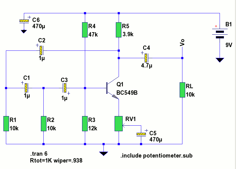
The core components of the Colpitts oscillator include a transistor, which acts as the active amplifying element, and a tank circuit comprising an inductor and two capacitors. The values of these components determine the oscillation frequency. The tank circuit is crucial as it sets up the resonant frequency, which can be calculated using the formula:
\[ f = \frac{1}{2\pi\sqrt{LC}} \]
where \( f \) is the frequency, \( L \) is the inductance in henries, and \( C \) is the total capacitance in farads. The capacitors are typically arranged in series and parallel configurations to achieve the desired capacitance value.
The circuit may also include additional components such as resistors for biasing the transistor and ensuring stable operation, as well as a power supply to provide the necessary voltage to the circuit. It is important to select components that can handle the frequency range specified, ensuring minimal phase noise and distortion during oscillation.
In practical applications, the output of the Colpitts oscillator can be used to drive other circuits, serve as a clock signal for digital systems, or be modulated for communication purposes. The design is favored for its simplicity and effectiveness in generating stable frequencies over a wide range. Proper layout and shielding techniques should be employed to minimize interference and maintain signal integrity in high-frequency operations.Colpitts 1MHz To 20 MHz Crystal Oscillator Circuit This is a simple Colpitts crystal oscillator for 1 to 20 MHz, PARTS.. 🔗 External reference
Related Circuits
A low-frequency test oscillator designed for testing tone controls and conducting experiments. The low-frequency test oscillator serves as a versatile tool in audio engineering, particularly for evaluating tone control circuits and facilitating various audio experiments. This device generates sinusoidal waveforms...
A crystal oscillator operates at a frequency of 51 MHz, which corresponds to the third harmonic of a 17 MHz fundamental frequency. Depending on the specific structure used, the drain-gate capacitance can be selected within a range of 0.5...
A quartz crystal tester is required to determine the functionality of a crystal, indicating whether it is operational or defective. This tester features an LED light indicator. A quartz crystal tester is an essential tool for evaluating the condition of...
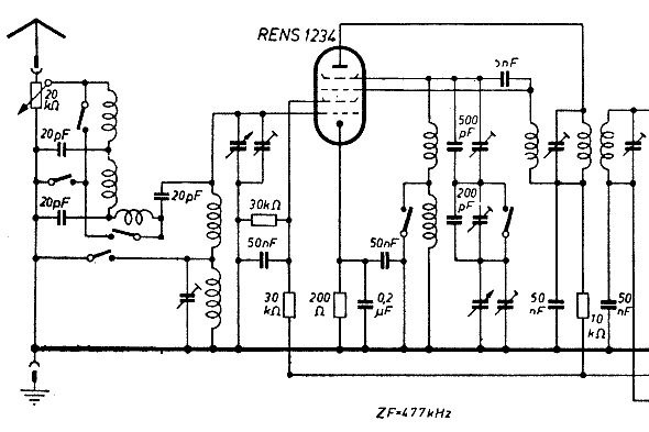
The schematic of the mixer section illustrates an oscillator. The oscillator's LC circuit has only two connections to the valve and does not include a tap or tickler coil. Oscillations will only occur if the tube provides a negative...
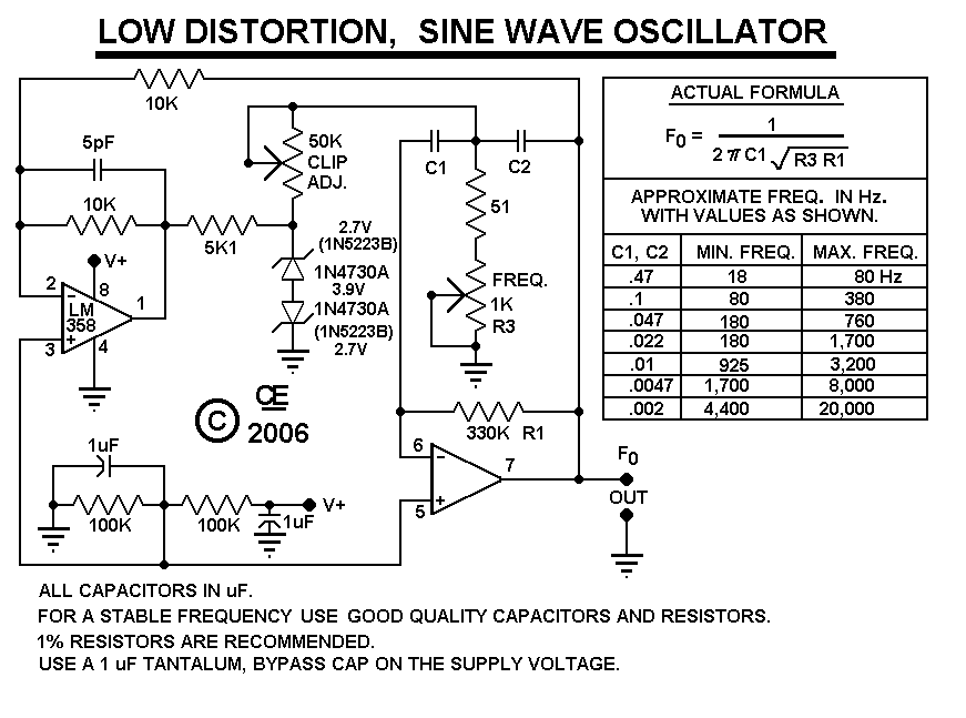
After constructing the device, adjust the frequency to the desired level using the "Frequency Control." Then, utilize an oscilloscope to fine-tune the waveform for optimal performance with the "Clip Control." The sharp rise and fall times of square waves...
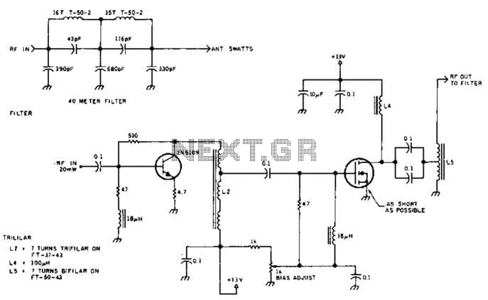
The circuit illustrated is designed to generate up to 5 watts of RF output in the 40-meter (7 MHz) amateur band. The coils depicted are wound on toroidal cores from Armdon Associates Inc., with part numbers provided in the...