
Negative Resistance Oscillators

The oscillator circuit described is a fundamental component in various electronic applications, particularly in RF (radio frequency) and communication systems. The oscillator's operation hinges on the balance between negative and positive resistances, allowing for sustained oscillations. The use of a virtual cathode generated by the suppressor electrode is a critical aspect, as it facilitates the necessary conditions for oscillation by controlling the flow of electrons.
In practice, the design of this oscillator requires careful selection of components to ensure stability and performance. The choice of the LC circuit elements—inductors and capacitors—must be made to match the desired frequency of oscillation. Additionally, the high resistance connected to the suppressor must be optimized to maintain the desired biasing conditions without introducing excessive losses.
The integration of a bypass capacitor between the suppressor and screen electrodes is essential for AC signal coupling while preventing DC bias interference. This arrangement enhances the oscillator's efficiency and responsiveness to varying input signals, making it suitable for applications that demand high-frequency stability and low distortion.
Furthermore, the ability to adjust the control-grid potential allows for fine-tuning of the oscillator's performance, enabling it to adapt to different operating conditions or requirements. This flexibility is particularly beneficial in experimental setups or environments where precise frequency control is necessary.
Overall, the described negative resistance oscillator circuit exemplifies the innovative use of vacuum tube technology in electronic design, paving the way for advanced applications in signal generation and amplification.The schematic of its mixer part shows such an oscillator. The oscillator LC circuit only has two connections to the valve. It has no tap or tickler coil. Oscillations will only the occur, if the tube provides a negative resistance which compensates the losses in the LC circuit. The negative resistance has to be smaller than the positive resistance of the LC circuit. Here the screen-grid and plate electrodes are both positive, and the suppressor is sufficiently negative to produce a virtual cathode between the suppressor and screen. A high resistance is placed between the suppressor and its bias potential, and the suppressor and screen electrodes are tied together with a by-pass condenser.
With this arrangement the screen-grid circuit offers a negative resistance to alternating currents. This is because the screen and suppressor electrodes are at the same potential with respect to alternating currents, and, if the potentials of both electrodes vary together, the current to the screen will decrease with increasing potential, and vice versa. The reduction in screen current comes about because the screen current consists largely of electrons that have returned from the virtual cathode produced by the negative suppressor.
As the suppressor-grid potential increases, more electrons are drawn from the virtual cathode to the plate, leaving fewer to return to the screen and hence reducing the screen current. The magnitude of the negative resistance obtained in this manner can be controlled by varying the control-grid potential.
With ordinary tubes values as low as 3000 or 4000 ohms are obtainable. A number of other negative resistance arrangements using vacuum tubes have been proposed but none of these except the magnetron, [which is discussed above, ] has had much practical use. Negative resistances obtained from tubes can be used as ordinary circuit elements, and make it possible to achieve circuit behaviors not realizable with positive circuit elements.
Thus it is possible to devise amplifiers, oscillators, etc. , based upon circuits containing negative resistance elements, although none of these arrangements except the dynatron oscillator have been used to any extent. The negative plate-cathode resistance of a dynatron can be used to produce oscillations by connecting a parallel resonant circuit in series with the negative resistance as shown in Fig.
198a. Such an arrangement will oscillate provided the negative plate resistance is less than the parallel resonant impedance ofthe tuned circuit. Also, if the grid bias is such that the negative resistance is just barely low enough for oscillation, the frequency stability with respect to tube conditions is extremely high and the oscillation is practically sinusoidal.
Such oscillators are sometimes used for laboratory or test oscillators, and are particularly satisfactory when combined with automatic amplitude control so as to maintain the tube conditions on the threshold of oscillation at all times, as discussed below. Negative resistances obtained in other ways can be used in similar manner to produce oscillations. Thus the oscillator of Fig. 198b employs the negative resistance arrangement of Fig. 83, and has the advantage over the dynatron in that negative resistance obtained by secondary emission is relatively unstable at times.
Synchronization between oscillations related by harmonies is discussed in the paper by Isaac Koga, A New Frequency Transformer or Frequency Changer, Proc. I. R. E. , vol. 15, p. 669, August, 1927. Also see U. S. Patent 1, 527, 228 issued to Schelleng; and J. Groszkowski Frequency Division, Proc. I. R. E. , vol. 18, p. 1960, November, 1930. `For further information about the dynatron and its uses see Albert W. Hull, The Dynatron, a Vacuum Tube Possessing a Negative 🔗 External reference
Related Circuits
The multiplication operation required to generate a signal with a frequency equal to the difference of the input frequencies can be implemented in various ways. A multiplied signal typically appears when two signals are added and subsequently processed through...
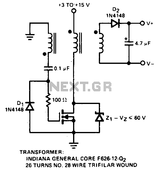
A simple method for generating a low-power voltage supply of opposite polarity from the main supply. A self-oscillating driver produces pulses at a repetition frequency of 100 kHz. When the VMOS device is off, capacitor C is charged to...
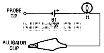
The continuity tester consists of a battery and a lamp connected in series, with one end of the circuit terminated with an alligator clip and the other end connected to the probe tip. The continuity tester is a fundamental...
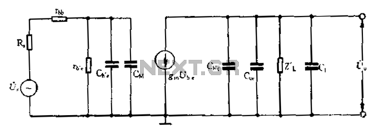
Common emitter amplifier circuit with resistance and capacitance coupling. The common emitter amplifier circuit is a fundamental configuration in analog electronics, widely utilized for its ability to amplify voltage signals. This circuit employs a bipolar junction transistor (BJT) as the...
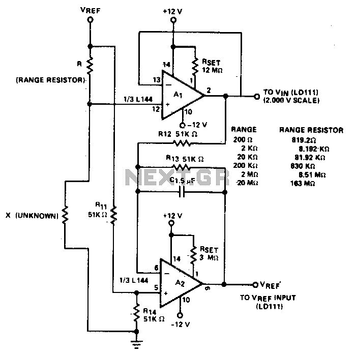
The circuit accurately measures up to 20M when used with a buffer amplifier (Al) that has a low input bias current (IiN) of less than 30 nA. It utilizes two of the three amplifiers found in the Siliconix L144...
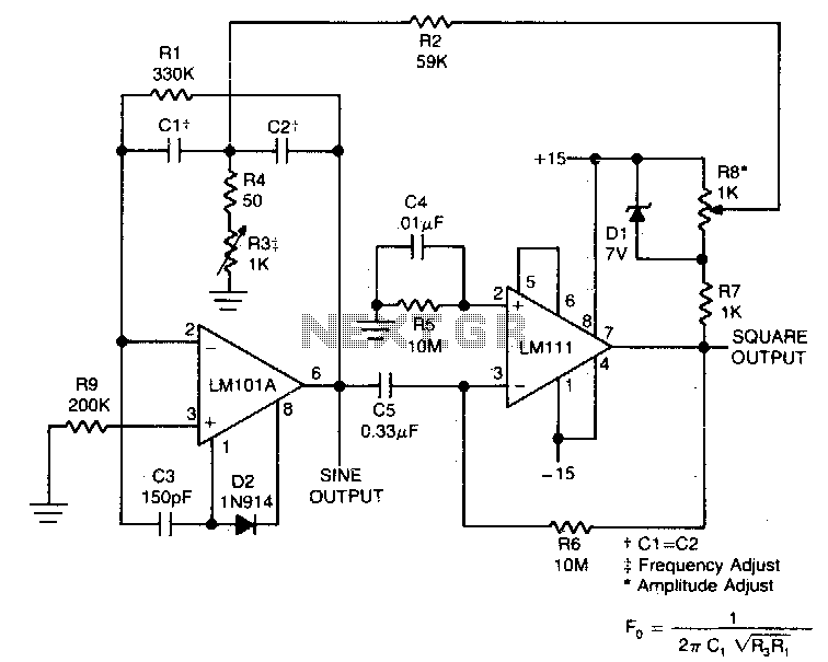
This circuit will provide both a sine and square wave output for frequencies ranging from below 20 Hz to above 20 kHz. The frequency of oscillation can be easily adjusted by changing a single resistor. This circuit is designed to...