
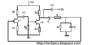
Colpitts Crystal Oscillator

To design a resonant circuit that achieves a specific frequency, the following steps can be employed:
1. **Determine the Desired Frequency**: Clearly define the target frequency (f) in hertz. This will serve as the basis for selecting the L and C values.
2. **Calculate Inductance and Capacitance**: Rearranging the resonant frequency formula allows for the calculation of either L or C when the other component is known. For example, if a specific inductance value is chosen, the corresponding capacitance can be calculated using C = 1 / (4π²f²L).
3. **Select Component Values**: Choose standard values for L and C that are readily available in the market. It is advisable to consider the tolerance and ratings of the components based on the application's requirements.
4. **Incorporate Resistance**: While resistance does not affect the resonant frequency directly, it is important to include it in the design to manage the circuit's bandwidth and quality factor (Q). The Q factor can be calculated using Q = f / Δf, where Δf is the bandwidth. Select R values that will provide the desired Q for the application.
5. **Simulation and Testing**: Before finalizing the design, it is prudent to simulate the circuit using software tools to verify the frequency response and make adjustments as necessary. Prototyping the circuit will also help in confirming the theoretical calculations.
By following these guidelines, a suitable combination of L, C, and R can be determined to achieve the desired frequency in a resonant circuit while ensuring optimal performance.Hey, Just wondering how to choose my L,C,R variables to achieve a desired frequency. Do I just choose any combination that yields X Mhz = 1 / ( 2pi *.. 🔗 External reference
Related Circuits
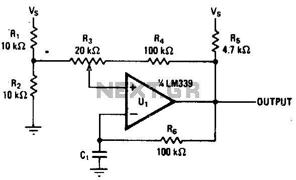
Varying the amount of hysteresis in this comparator circuit allows for smooth adjustment of output frequencies within the range of 740 Hz to 2 kHz. The hysteresis level, in combination with the time constant formed by resistor R6 and...
An oscillator circuit is an electronic circuit that produces a periodic signal. The term quadrature refers to a fourth (1/4) phase shift of a full wave cycle (1/4 of... An oscillator circuit is a fundamental component in various electronic systems,...
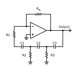
Phase-shift oscillator. An oscillator in which a network has a phase shift of 180 degrees. A phase-shift oscillator is a type of electronic oscillator that generates a sinusoidal output signal. It typically consists of an amplifier and a phase-shifting network...
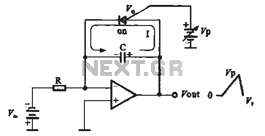
A sawtooth voltage-controlled oscillator operates by first generating a negative potential maximum at the output of the comparator. This output is then fed to the inverting input terminal through resistor R1, which is part of the relaxation oscillator. The...
The Wien bridge oscillator utilizes a balanced Wien bridge as its feedback network. Two-stage common source amplifiers provide a 360-degree phase shift to the signal. The attenuation of the bridge is calculated to be 1/3 at the resonant frequency....
The Hartley oscillator is an enhancement of the Armstrong oscillator. While its frequency stability is not the highest among oscillators, it is capable of generating a broad spectrum of frequencies and is straightforward to tune. The Hartley oscillator operates...