
Colpitts Oscillator Tutorial and Oscillator Design

The Colpitts oscillator is a type of electronic oscillator that utilizes a tank circuit composed of inductors and capacitors to produce sine wave signals. The fundamental operation of the Colpitts oscillator is based on the principles of resonance in LC circuits, where the energy oscillates between the inductor and capacitors at a specific frequency determined by their values.
The tank circuit typically consists of a single inductor (L) and two capacitors (C1 and C2) connected in series. The output frequency of the oscillator can be calculated using the formula:
\[ f = \frac{1}{2\pi \sqrt{L \cdot \frac{C1 \cdot C2}{C1 + C2}}} \]
In this configuration, the capacitors C1 and C2 form a voltage divider, which is crucial for the feedback mechanism that sustains oscillation. The inductor provides the necessary phase shift and energy storage required for the oscillation process.
The active component used in the Colpitts oscillator can be a transistor or an operational amplifier. The transistor is configured in a common emitter or common collector arrangement, providing the necessary gain to compensate for losses in the circuit. The feedback loop is established by connecting the output of the tank circuit back to the input of the transistor, ensuring that the oscillation continues.
One of the significant advantages of the Colpitts oscillator is its ability to generate stable frequencies with low distortion, making it suitable for various applications, including RF signal generation, audio synthesis, and clock generation in digital circuits. The design can be easily adjusted by changing the values of the capacitors and inductor, allowing for fine-tuning of the output frequency.
In summary, the Colpitts oscillator is a versatile and widely used circuit in electronics, leveraging the principles of LC resonance to produce reliable sine wave outputs. Its design simplicity and frequency stability make it an essential component in many electronic systems.Colpitts Oscillator Tutorial and the theory behind the design of the Colpitts Oscillator which uses a LC Oscillator tank circuit to generate sine waves.. 🔗 External reference
Related Circuits
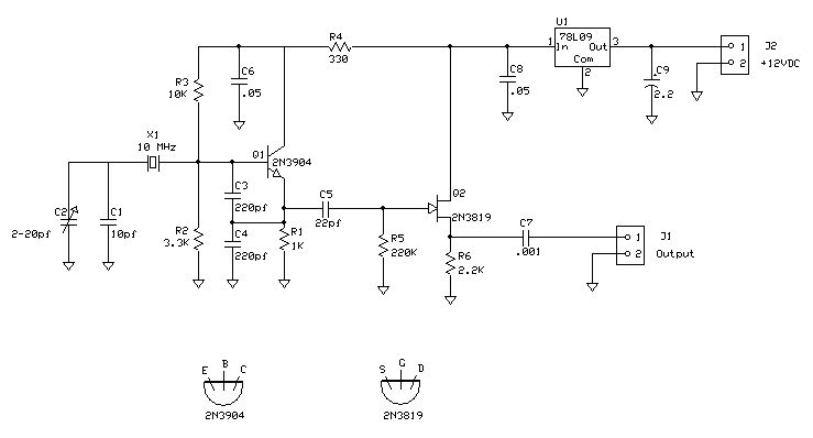
There are three oscilloscopes currently available: an older optoelectronics Opto-7000 that is rarely used, a newer Mitronics MIC-1028, and a recently acquired used Tektronics 2236 oscilloscope purchased at Dayton in 2009, which features a built-in frequency counter. During a...
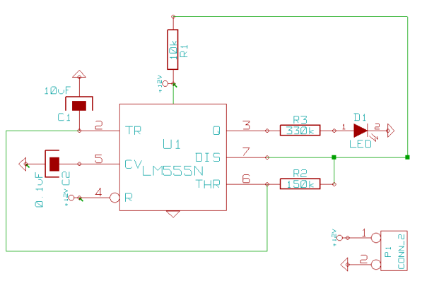
This page outlines how to create a simple theft deterrent that can be quite effective. The concept involves using a flashing red LED to indicate that the vehicle is protected. This device serves to safeguard the car from potential...

This circuit operates at or near series resonance. It has fair to poor circuit design with parasitics, touch to tune, and fair frequency stability. The circuit in question is designed to function at or near its series resonance frequency, which...
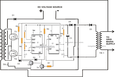
A single IC 556 has been utilized to generate PWM pulses. One half of the IC is configured as a high-frequency generator, which supplies the other half of the IC, set up as a pulse width modulator. The modulating...

FAN7710 Ballast Control circuit design for Compact Fluorescent Lamps electronic project. The FAN7710 is a specialized integrated circuit designed for the control of ballast systems in compact fluorescent lamps (CFLs). This circuit typically operates in a high-frequency range, facilitating efficient...
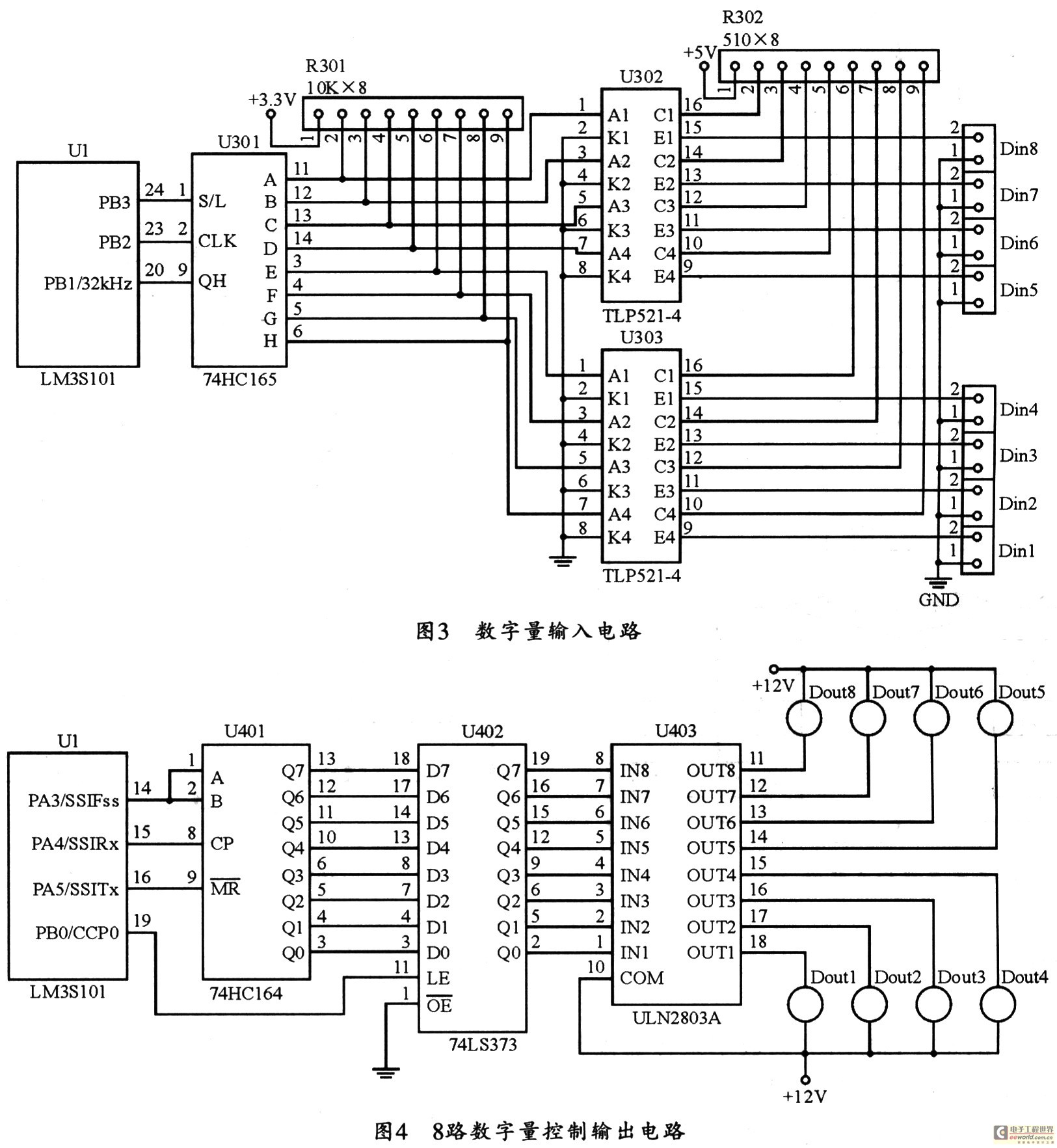
The figure utilizes a controller as the primary equipment for gathering and controlling digital data within an on-site monitoring system. The stability of on-site control operations is crucial to the overall system performance. Therefore, a simple and stable structure...