
Butler common base oscillator

No description available.
Related Circuits

The circuit consists of two oscillators, both working at about 465 kHz. One uses an if transformer and the other uses an inductor (the search coil LI). The oscillators are coupled by a capacitor (10 pF). A beat note...
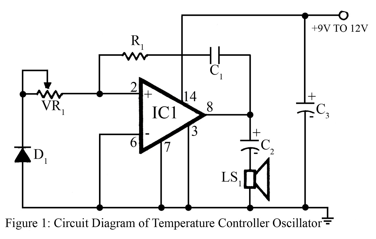
The output frequency or tone of this oscillator circuit varies with the temperature at which the input germanium diode is maintained. The reverse resistance of D1 ranges from 500 ohms to 10 k ohms when the temperature fluctuates between...
In applications where good frequency stability is essential, such as radio transmitters, basic LC oscillators may not maintain their frequency without drifting. This drift can be caused by small changes in supply voltage, although stabilized power supplies can help...
Running Message Display Circuit Diagram. This circuit is based on the CD401 IC. Features: Light emitting diodes are advantageous due to their smaller size. The Running Message Display Circuit utilizes the CD401 integrated circuit, which is a versatile component in...
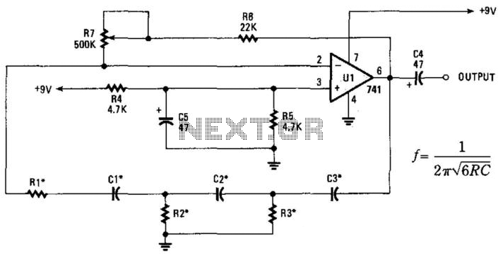
This phase-shift oscillator is suitable for audio oscillator applications. Adjust R7 to achieve a good sine wave. An amplifier gain of 29 is necessary for oscillation. If C=C1=C2=C3 and R=R1=R2=R3: Typically, R will range from 1 to 100 kOhm...

Q is the transistor, L1 and L2 form a resonant circuit, with L2 also serving as a feedback network. The feedback voltage is transmitted to the transistor base through the coupling capacitor Cb. Figure 2 illustrates the communication channel,...