
Combination Lock With Auto Reset

The combination lock circuit employs a 4-digit input mechanism, which can be implemented using a keypad or a series of momentary push buttons. Each button corresponds to a digit from 0 to 9, allowing the user to input their desired combination. The circuit is designed using CMOS technology, which contributes to its low power consumption, making it suitable for battery-operated applications.
Upon entering the correct combination, the circuit activates a relay or a transistor switch, which can control a locking mechanism or an alarm system. The auto-reset feature ensures that if the incorrect combination is entered, the system will automatically reset after a specified period, preventing unauthorized access attempts.
The power supply for the circuit can range from 9 to 15 volts, providing flexibility for various applications. A voltage regulator may be included to ensure stable operation within this range. Additionally, the circuit can incorporate indicators, such as LEDs, to provide visual feedback during the input process or to signal successful entry of the correct combination.
Overall, this combination lock circuit is an efficient and reliable solution for securing access to sensitive areas or devices, leveraging the advantages of CMOS technology for enhanced performance and energy efficiency.This circuit function for combination lock with auto reset. 4 Digit Enter Combination, C-Mos Design, Low Standby Power, and 9 to 15 Volt Operation .. 🔗 External reference
Related Circuits
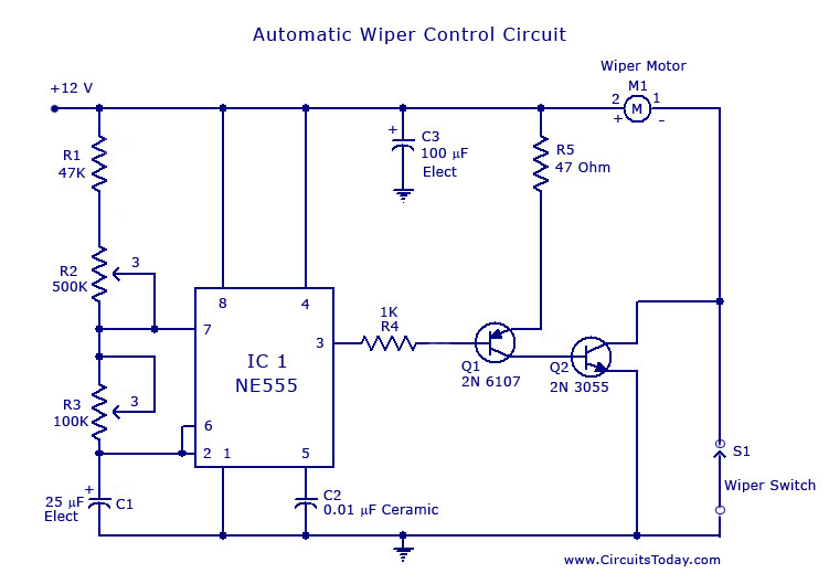
A circuit for car windshield/wiper motor speed control built using an NE 555 IC. This enables intermittent windshield wiper control, which changes the sweep rate to 10 seconds. The circuit utilizes the NE 555 timer IC configured in astable mode...
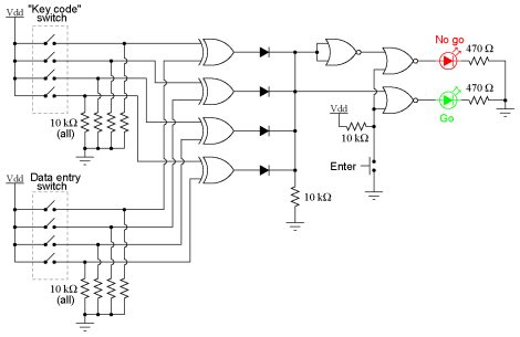
This experiment can be constructed using a single 8-position DIP switch, although utilizing two switch assemblies may facilitate a better understanding of the concept. One switch assembly is designated to hold the correct code for unlocking the lock, while...
CMOS circuits are recognized for their low current consumption, which is particularly crucial for battery-powered applications. However, oscillators typically demand a significant amount of current. This proposed oscillator circuit achieves a very low current consumption of approximately 3 µA....
This automatic light dimmer circuit enables the gradual control of a lighting system, allowing it to turn on or off slowly. The operation of the circuit is as follows: when switch S1 is closed, capacitor C1 charges slowly. Once...
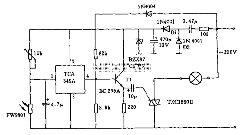
A 200W lamp switch control operates at a power supply voltage of 220V. It automatically turns the light on or off based on ambient illumination levels, specifically activating at approximately 100 lux. In low light conditions, a time-sensitive resistor...
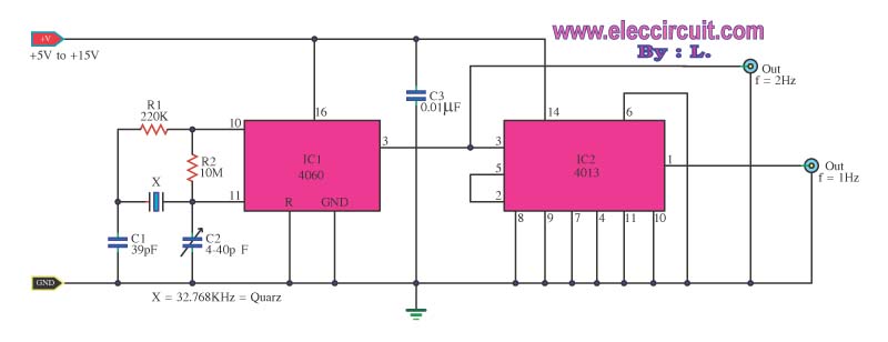
This is a standard digital clock circuit with a frequency of either 1 Hz or 2 Hz. It can be utilized in a conventional clock circuit. The circuit comprises IC-4060 and IC-4013. The digital clock circuit operates by utilizing the...