
Automatic lamp dimmer circuit

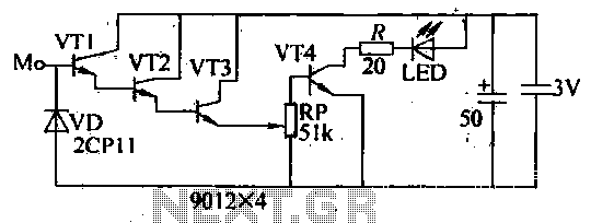
The automatic light dimmer circuit utilizes several key components to achieve its functionality. The primary components include a switch (S1), a capacitor (C1), a transistor (T1), a light-dependent resistor (LDR), a silicon-controlled rectifier (SCR), a diode (D1), and a potentiometer (P2).
When the circuit is powered, the closing of switch S1 initiates the charging process of capacitor C1. The slow charging is crucial as it determines the time delay before the LED lights up. The voltage threshold of 0.6 volts across C1 is significant as it activates transistor T1. This transistor acts as a switch that controls the current flow to the LED based on the voltage level of the capacitor.
The interaction between the LED and the LDR is essential for the dimming effect. As the LED illuminates, the resistance of the LDR decreases, which allows the SCR to conduct sooner than it would otherwise, thereby enhancing the gradual illumination of the lighting system.
The gradual dimming effect when switch S1 is opened is achieved through the slow discharge of the capacitor C1. This characteristic ensures that the LED does not turn off abruptly, providing a more aesthetically pleasing transition from bright to dark.
The adjustment of potentiometer P2 plays a critical role in setting the operational parameters of the circuit. By ensuring that the anode voltage of diode D1 is approximately 0.7 volts, the circuit is optimized for performance, allowing the capacitor to maintain a standby voltage of around 0.5 volts when the lights are off.
Overall, this automatic light dimmer circuit is a practical solution for applications where gradual lighting control is desired, enhancing both functionality and user experience.This automatic light dimmer circuit makes it possible to control a lighting system so that it turns on or off slowly. The circuit works this way: when switch S1 is closed, the capacitor C1 is slowly charged. Once the voltage at C1 reaches 0. 6, transistor T1 begins to conduct and the LED also begins to light. If the capacitor voltage increases furt her, then transistor T1 conducts more current and in return the LED lights brighter. If the LED lights up, the LDR resistance decreases causing the SCR to conduct periodically earlier. This tehnique causes the lighting system to turn on slowly. On the other hand if switch S1 is turned off, meaning the switch is opened, the LED does not immediately turn off since the capacitor voltage at the base of T1 discharges slowly. The LED slowly dims until finally turns off. This causes the lighting dim out before it finally turns off. Potentiometer P2 must be set so that the anode voltage of D1 is about 0. 7 volts. If this is done, the capacitor voltage will be around 0. 5 volts during standby, meaning lights off. We aim to transmit more information by carrying articles. Please send us an E-mail to wanghuali@hqew. net within 15 days if we are involved in the problems of article content, copyright or other problems.
We will delete it soon. 🔗 External reference
Related Circuits

This decade box can be configured for any resistance value between 10 and 11.1 in 10-stop increments. A switch is employed to set various RC configurations. It is recommended to utilize precision components in the circuit. If feasible, verify...

The TEA5551T monolithic integrated radio circuit can be utilized to design an AM radio receiver circuit intended for portable use with headphones. This circuit incorporates all necessary components for a complete AM radio receiver, including a fully integrated AM...
The internal disconnection circuit for a blanket operates on the principle of induction. It includes a wire approximately 2 cm in length that senses the proximity of a charged mains power source. When the sensing wire is close to...

Transistors Q1 and Q2, along with resistors R1 through R7, form the input balancing stage that measures the resistance between points X and Y. This stage operates as a bridge circuit, incorporating resistors R1, R2, R6, R7, and the...
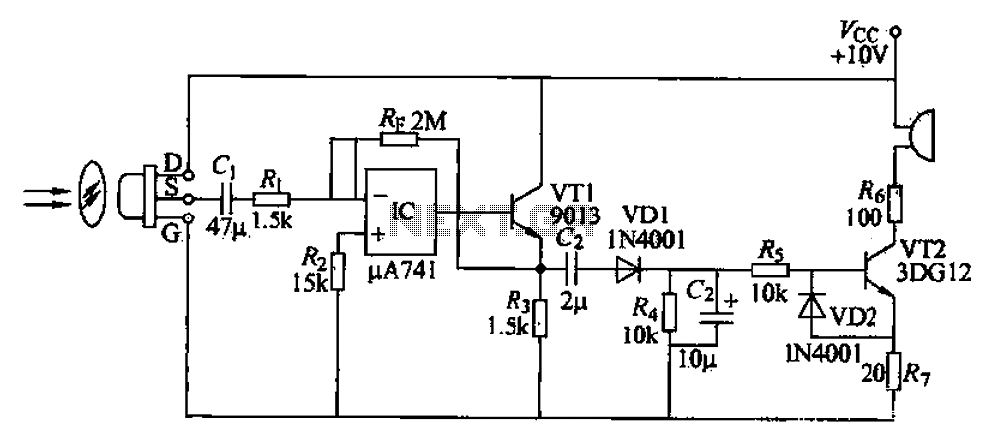
A simple burglar alarm circuit utilizes a pyroelectric sensor (IRA-E100SZI). When human movement is detected, it triggers an electric buzzer alarm. The sensor receives signals through an AC amplifier, which is then converted by a rectifier circuit into a...
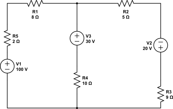
Using the superposition theorem, it is necessary to determine the current at all three nodes of the circuit. The current from the source, denoted as i_1, represents the current through V1 when other voltage sources are shorted out, in...