
Strobe Light Circuit

The strobe light circuit is designed to produce high-intensity flashes of light at specified intervals. It typically consists of a power supply section, a control circuit, and a strobe light element. The power supply converts the 220V AC mains voltage into a suitable DC voltage, which powers the control circuit and the strobe light.
The control circuit may include components such as a timer, a microcontroller, or a simple oscillator that determines the frequency and duration of the light flashes. Safety features should be implemented to prevent electric shock, including proper insulation, fuse protection, and the use of relays to isolate high voltage components from user-accessible parts.
The strobe light itself can be an incandescent bulb, LED array, or a xenon flash tube, depending on the desired brightness and application. The design must ensure that all components are rated for the voltage and current they will encounter during operation.
It is essential to follow safety guidelines when working with high-voltage circuits, including using insulated tools, wearing protective equipment, and ensuring that the circuit is de-energized before making any adjustments or measurements. Proper grounding and circuit layout will also mitigate risks associated with electrical shock and equipment damage.Attention! This strobe light circuit is connected to 220V, so measurements and experiments are very dangerous even after unplugging it from the mains. P1 p.. 🔗 External reference
Related Circuits
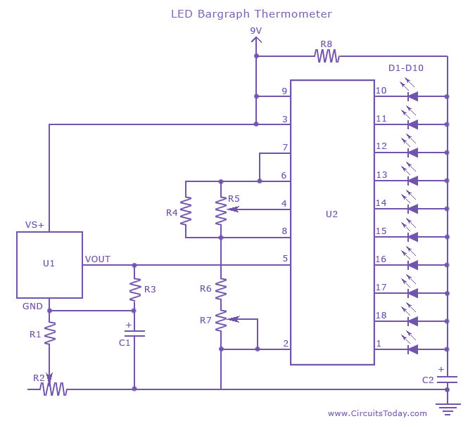
An LED thermometer that can function as a temperature sensor or temperature measurement circuit, utilizing the LM34 for Fahrenheit display or the LM35 for degree Celsius display. The LED thermometer circuit is designed to provide accurate temperature readings using either...
This modified Hartley oscillator can be utilized to attract new friends or serve as a replacement doorbell. The modified Hartley oscillator is a type of electronic oscillator that generates a continuous waveform, typically a sine wave, using an LC (inductor-capacitor)...
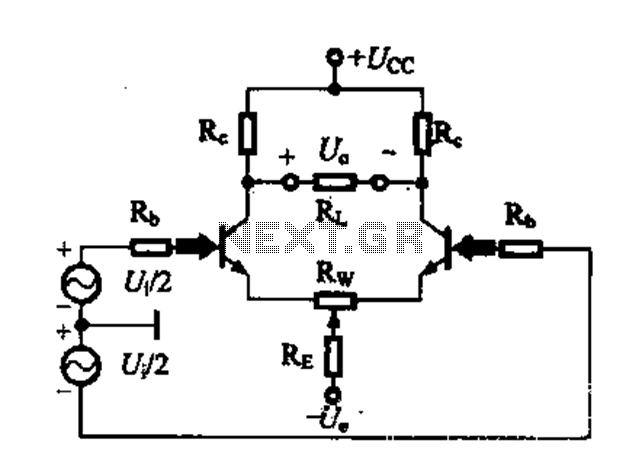
A differential amplifier circuit can be configured in four different connection methods, allowing for a comparison of characteristics such as gain and common-mode rejection ratio (CMRR). This analysis focuses on symmetrical circuits and their performance in handling common-mode signals. The...
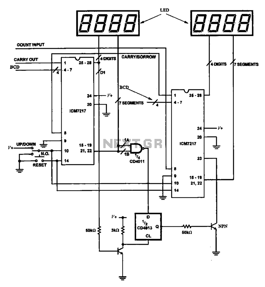
Figure 8 illustrates a potential digital counter circuit. This circuit employs two ICM7217 integrated circuits, with each controlling four digital display tubes. The digital counter circuit primarily utilizes the ICM7217, a highly integrated chip designed for driving seven-segment displays. Each...
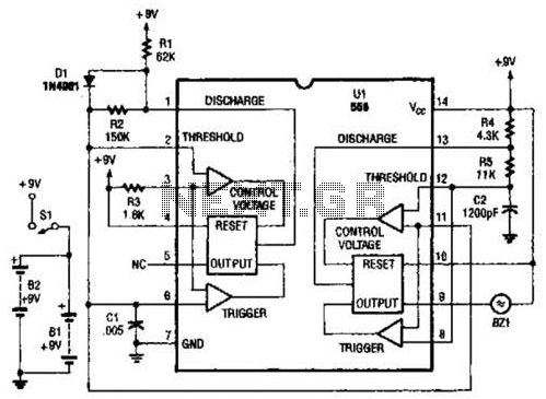
The two timers in the bug repeller exhibit notable characteristics. Both have their thresholds set externally; the oscillator on the left operates with a 50% duty cycle, while the oscillator on the right functions as a voltage-controlled oscillator (VCO). The...
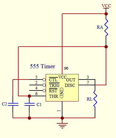
The timer circuit is utilized in various projects and is primarily categorized into two types. The first type is an analog RC circuit, where the charging of the capacitor determines the timing of the circuit. This type has a...