
PC-Based Data Logger circuit description with PCB layout

The PC-based data logger serves as an essential tool in physics laboratories, enabling the automation of experiments and the monitoring of various physical variables. This device interfaces with a computer to collect data from sensors, which may include temperature, pressure, voltage, and other measurable parameters. The data logger typically features multiple input channels, allowing for the simultaneous monitoring of several variables.
The system architecture usually consists of a microcontroller or dedicated data acquisition hardware that interfaces with the sensors. The data acquisition system converts the analog signals from the sensors into digital data that can be processed by the computer. The software component of the data logger provides a user-friendly interface for configuring experiments, visualizing data in real-time, and storing data for later analysis.
In addition to logging data, the software often includes capabilities for data analysis, allowing users to generate graphs, perform calculations, and export results in various formats. This functionality is crucial for educational purposes, as it aids in the understanding of physical principles through hands-on experimentation.
Furthermore, the design of the data logger may incorporate features such as wireless communication for remote monitoring, data encryption for security, and power management systems to ensure long-term operation during experiments. Overall, the PC-based data logger is a versatile and valuable instrument in the study of physics, enhancing both teaching and research capabilities.PC-based data logger used in physics laboratories for automating simple experiment and or monitoring slowly varying physical variable various pc-based project . 🔗 External reference
Related Circuits

The add-on circuit presented here is useful for stereo systems. This circuit has provisions for connecting stereo outputs from four different sources or channels as inputs, with only one of them selected and connected to the output at any...
The antenna tuning circuit can accommodate 1/2 wave length antennas or higher, for input resistances of 50 Ohms which make it suitable for CB (Citizen Band) transceivers. C1 is for fine tuning and C2 is just for tuning. Turning...
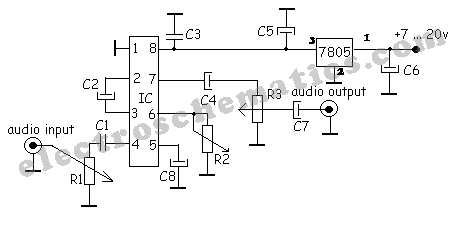
A simple audio compressor is designed using the SSM2165 integrated circuit (IC). There is limited explanation available regarding the schematic of this compressor circuit; however, special attention should be given to the capacitor used. The audio compressor circuit utilizing the...
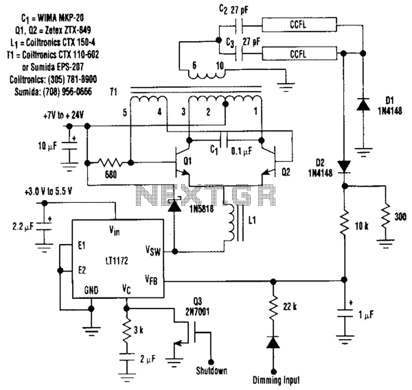
This circuit is a 92%-efficient power supply for cold-cathode fluorescent lamps (CCFLs), which are used to backlight LCDs in portable equipment. The efficiency depends heavily on the component types, particularly C1, Q1, Q2, L1, and T1, whose manufacturers are...
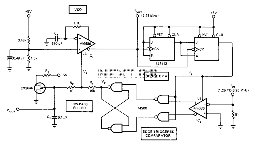
A circuit diagram of a phase-locked loop utilizes an AM686 latched comparator as a voltage-controlled oscillator, along with a TTL latch connected to generate edge-triggered comparators. The VCO and its comparison with the low-pass filter consisting of R1, R2,...
This single transistor audio mixer is utilized in an amplifier circuit design featuring a base-driven transistor, with its emitter being current-controlled. This audio mixer circuit employs a single transistor to facilitate the mixing of audio signals. The transistor operates in...