
Combinational Logic Circuits using Logic Gates

Combinational logic circuits are fundamental components in digital electronics, characterized by their ability to produce outputs based solely on the current inputs, without any memory of past inputs. These circuits employ various logic gates, such as AND, OR, NOT, NAND, NOR, XOR, and XNOR, to perform logical operations and implement complex functions.
Multiplexers, also known as data selectors, are devices that take multiple input signals and select one of them to be sent to the output based on the values of select lines. A typical multiplexer is designed with a specific number of inputs and outputs, along with control lines. For example, a 2-to-1 multiplexer has two input lines, one output line, and one control line. The output reflects the value of the selected input, depending on the state of the control line.
Encoders are another type of combinational logic circuit that converts input signals into coded output signals. For instance, a binary encoder takes multiple input lines and produces a binary representation of the active input. A common example is the 4-to-2 encoder, which has four input lines and produces a two-bit binary output corresponding to the active input line.
Solid-state switches utilize similar principles as traditional mechanical switches but are based on semiconductor devices. These switches can control the flow of current in a circuit with high reliability and speed, making them ideal for applications in automation and control systems. Solid-state switches can be implemented using transistors or other semiconductor devices, providing advantages such as reduced wear and tear compared to mechanical switches.
Overall, the study of combinational logic circuits and their applications in multiplexers, encoders, and solid-state switches is crucial for designing efficient digital systems and contributes significantly to advancements in electronics and computing technology.Electronics Tutorial about Combinational Logic Circuits that use Logic Gates to make Multiplexers, Encoders and Solid State Switches.. 🔗 External reference
Related Circuits
AN6884 is a logarithmic scale LED bar display driver that accepts a wide range of supply voltages, from 3.5V to 16V. This device is designed for use in voltage unit (VU) bar displays. The AN6884 is specifically engineered to drive...
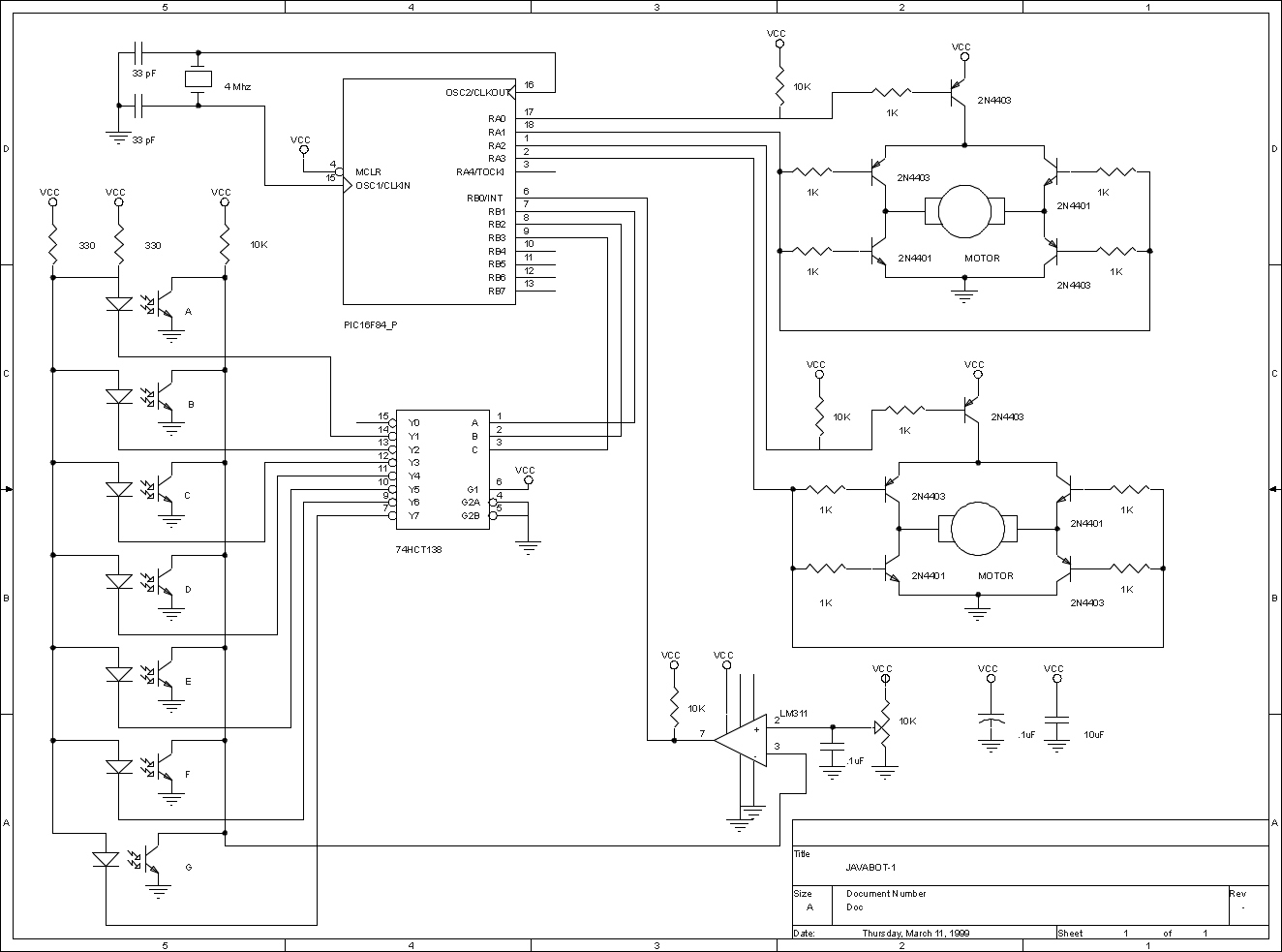
The JavaBot1 is a compact line-following robot engineered to trace a black line drawn on a dry erase board. It is specifically designed to navigate along very narrow curves. The JavaBot1 employs a differential drive mechanism, which allows it to...
Introduction The ignition timing lights commonly used range from simple neon to complex units. Neon timing lights have a drawback due to their low light output, necessitating operation in subdued lighting. This presents a safety hazard, as users tend...
This is a simple PWM modulator circuit. Comparing the message signal to a ramp or triangular waveform is the simplest way to produce a PWM signal. When the... The PWM (Pulse Width Modulation) modulator circuit operates by comparing a modulating...
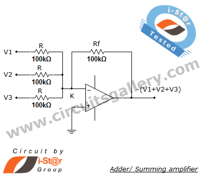
A summing amplifier, also known as an adder, is utilized to combine two or more signal voltages. This voltage adder circuit is straightforward and allows for the addition of multiple signals. It has a wide range of applications in...
The microphone amplifier/modulator is built around the LM324, which is a quad operational amplifier that provides sufficient quality amplification for the voice captured by the condenser microphone. The LM324 is a versatile quad op-amp that consists of four independent, high-gain,...