
Summing amplifier/ Inverting adder circuit using op amp 741

A summing amplifier circuit typically employs operational amplifiers (op-amps) configured to perform arithmetic addition of input voltages. The most common configuration is the inverting summing amplifier, where multiple input signals are fed into the inverting terminal of the op-amp through resistors. The non-inverting terminal is connected to ground. The output voltage is a weighted sum of the input voltages, with each input signal scaled by its corresponding resistor value. The relationship between the input voltages (V1, V2,..., Vn) and the output voltage (Vout) can be expressed by the formula:
Vout = - (R_f / R1 * V1 + R_f / R2 * V2 + ... + R_f / Rn * Vn)
where R_f is the feedback resistor and R1, R2, ..., Rn are the resistors connected to the inputs.
This configuration allows for flexibility in signal processing, making it suitable for applications such as audio mixing, where signals from various sources need to be combined while maintaining control over individual signal levels. The ability to adjust the gain for each input independently is achieved by selecting appropriate resistor values.
In cases where non-inverted output is required, a non-inverting summing amplifier can be implemented. This can be done by using a second op-amp stage that follows the inverting summing amplifier. The second stage can be configured to provide the desired gain and phase characteristics, allowing for greater versatility in circuit design.
Overall, summing amplifiers are essential components in various electronic applications, providing a means to combine multiple signals effectively while maintaining control over the output characteristics.Summing amplifier or an adder is used to sum two signal voltages. Voltage adder circuit is a simple circuit that enables you to add several signals together. It has wide variety of applications in electronic circuits. For example, on a precision amplifier, you may need to add a small voltage to cancel the offset error of the op amp itself. An audi o mixer is another good example of adding waveforms (sounds) together from different channels (vocals, instruments) before sending the combined signal to a recorder. You can change the gain or add another input without messing up with the gains of other inputs. Just remember that the inverting summing amplifier circuit inverts the input signals. That`s not a big deal. If you need the opposite polarity, all you have to do is to put an inverting stage before or after the summer.
🔗 External reference
Related Circuits
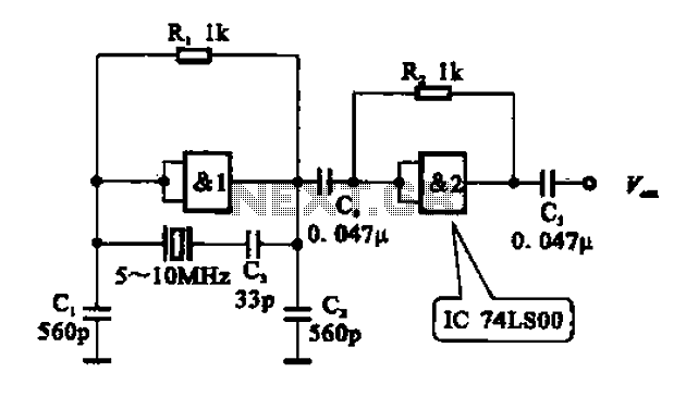
A crystal oscillator circuit comprises various gates as illustrated in the provided figures. Figure (A) represents a crystal oscillator circuit operating at 1 MHz, while figure (B) depicts a 20 MHz crystal oscillator circuit. Figure (C) shows a variable...
The IC1 is a 555 timer IC connected for astable operation. The clock pulses are fed to the IC2 via the 10K resistor. The IC2 is a 10-stage counter; output 6 (pin 5) is connected to RESET (pin 15),...
Implementing peak-detector circuits is straightforward with the CA3130, as illustrated in the schematic diagram of this circuit. The figure below presents the schematic diagram. The CA3130 is a high-performance operational amplifier that is well-suited for peak detection applications due to...

A simple and compact power supply electronic project can be designed using the LTM8008 Module SEPIC converter, which includes six post-regulators. This setup provides six outputs capable of delivering varying output currents for some of the outputs. The SEPIC...
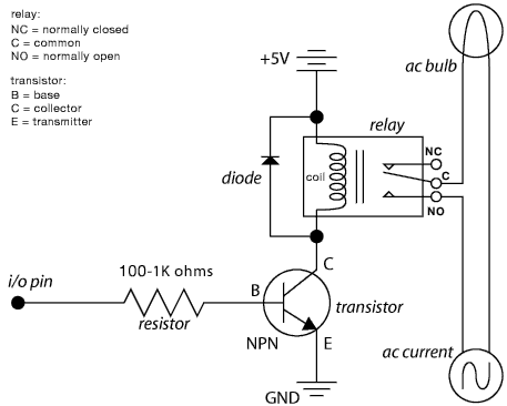
The schematic illustrates the Relay Wiring Circuit Diagram used to control an air conditioner or other high-current devices via a microcontroller. The relay wiring circuit serves as an interface between low-voltage microcontroller signals and high-voltage appliances, such as air conditioners....
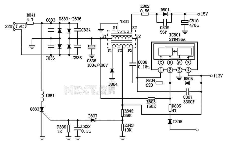
The Panasonic M12H switching power supply circuit is utilized in Panasonic models such as TC-230H, TC-2030DHN, TC-830D, and TC-840D. The circuit operates with an oscillation frequency that generates approximately 300V DC voltage at C836. The T801 transformer is involved...