
Command Station for DCC Adapter for Xpressnet

Xpressnet serves as a robust communication framework for model railway systems, allowing for seamless integration of various components. The architecture is based on the RS485 protocol, which is well-suited for multi-drop networks, enabling multiple devices to communicate over a single pair of wires. The choice of using half-duplex communication is significant, as it simplifies the wiring requirements while still allowing for efficient data transfer.
The Max485 or Max481 chips are pivotal in the conversion process, transforming the TTL level signals from the microcontroller into differential signals suitable for RS485 communication. This conversion is essential for maintaining signal integrity over longer distances, which is a common requirement in extensive model railway setups.
The implementation of pull-up and pull-down resistors on the differential lines is a critical design consideration to prevent the lines from floating when no devices are transmitting. This ensures that the communication lines remain stable and reduces the likelihood of erroneous data transmission.
The design also incorporates a visual feedback mechanism through an LED, which indicates the direction of data transmission. While this feature may not be essential for all users, it can aid in troubleshooting and ensure that the communication is functioning correctly.
The requirement for an external power supply in larger installations highlights the importance of power management in digital communication systems. Adequate power supply design is crucial to ensure that all devices receive the necessary voltage and current without overloading the system.
Furthermore, the recommendation to replace the Atmega32 with an Atmega644P underscores the need for scalability in design. The additional USART provided by the Atmega644P enhances the system's capabilities, allowing for more complex setups and improved communication options.
Finally, the emphasis on verifying the output voltage before connecting Xpressnet devices is a prudent safety measure. This step ensures that the devices are not subjected to incorrect voltage levels, which could lead to device failure or erratic behavior. The inclusion of error messages, such as the Err13 from the Roco Multimaus, provides users with immediate feedback on the system's operational status, facilitating quicker troubleshooting and maintenance.Xpressnet is a bus system for model railways to interconnect input devices, computer interfaces and stationary decoder or feedback detectors. Many commercial input devices (including the multi-mouse from Roco) are based on this bus. The following adapter enables OpenDCC to interface to Xpressnet devices. Xpressnet devices need a power supply of 12V. This voltage is created with an linear regulato from the supply of OpenDCC. On large Xpressnet installations, however, this power supply may be overloaded. In this case, the 12V should be generated with a powerful external power supply. The fuse F1 must be left out in this case. SJ1 should be left open. Xpressnet uses a half-duplex RS485 connection. The baud rate is 62. 5 kBaud, 9 bit are used, no parity, one stop bit. The chip Max485 (or Max481) takes the data from the serial interface of the processor and converts it into the R485 differential signal. While not required, it is strongly recommended that slew-rate limited transmitters be used to minimize high frequencies on the bus, and thus help avoid possible termination/reflection issues.
A LED displays the transmission direction (normally not needed). By testing different transcievers I found that the differential lines of RS485 may come to an undefined state, if neither master nor slave is sending. A pullup resitor of 1k5 to 5V on line A and a pulldown of 1k5 to GND on line B is recommended. The adapter could be plugged on the pin headers for JP1 and JP2 boat and on the interface for ISP. Only the power supply (+15 V) for regulator for Xpressnet must be connect with a separate wire from the power supply plug of the command station.
I`m using long wire-wrap pin header to get a distance of 20mm between the PCBs. The processor Atmega32 of OpenDCC must be replaced by an Atmega644P, to support the second USART. Important is the suffix P (PicoPower), only this type contains two USARTs. Now power up the adapter and check the output voltage. Only after this Xpressnet devices should be connected. The Roco Mulitmaus reports Err13 when it cannot connect to the command station. 🔗 External reference
Related Circuits
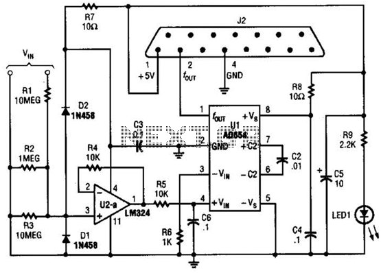
The adapter comprises a voltage-to-frequency converter integrated with a signal conditioning and protection circuit. J2 interfaces with the game port of a personal computer. Additional software references are available for use with this circuit. The voltage-to-frequency adapter functions by converting...
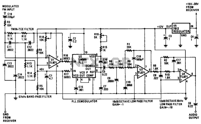
The operational amplifier (Op Amp) U1 and its associated components form a 67-kHz bandpass filter. A twin-T network, consisting of four 1100-ohm resistors and four 0.0022-microfarad capacitors, is integrated into the feedback loop of the op amp. This configuration...
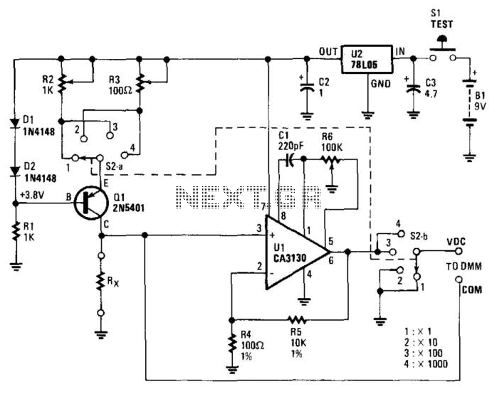
The circuit includes a 5-V regulator, a constant-current source (D1, D2, and Q1), and an operational amplifier (op amp) gain stage (U1). Power is supplied by a 9-V battery, which is regulated to +5 V DC by a three-terminal...
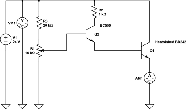
The device shows a voltage of 24V at no load on pins +4, 5 and -7, 8. This configuration is referred to as a passive power injector. When a current draw of 1A was attempted from the device, it...
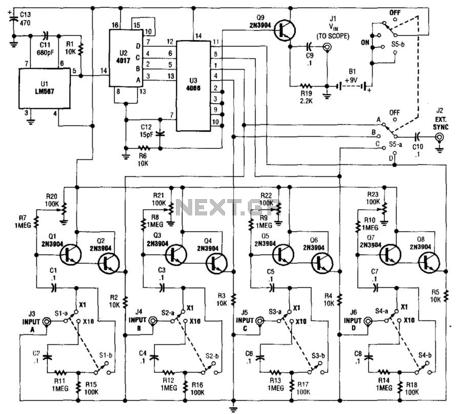
This simple adapter utilizes an oscillator (567) to drive a counter (U2) and a switch (U3) that selects the output of one of four scope preamps (Q1/Q2 through Q7/Q8) and feeds it to buffer Q9 and output jack J1....
You need a power supply for a project, but only have a DC adapter available, so you can't use my AC power adapter trick (Project 05). This little project came about because a reader had just this problem, and...