
Low-Ohms Adapter

The circuit is designed for precise measurement and testing of resistive components by utilizing a regulated power supply and a constant current source. The 5-V regulator ensures stable operation of the circuit, while the constant current source, facilitated by the diodes D1 and D2 and transistor Q1, maintains a consistent test current, which is critical for accurate resistance measurements.
The operational amplifier (U1) acts as a gain stage, amplifying the voltage drop across the resistor under test when higher ranges are selected. This amplification is essential for measuring low-resistance values accurately, as it increases the sensitivity of the measurement. The switch S2A allows the user to select between different test currents and ranges, providing versatility for testing various resistor values.
The multiturn trimmer potentiometers R2 and R3 allow for fine adjustment of the test current, ensuring that the circuit can accommodate a wide range of resistances without exceeding the limits of the DMM. The adjustment of R6 is crucial for calibrating the op amp, ensuring that any offset is corrected, and that the output accurately reflects the voltage across the resistor under test.
Overall, this circuit is an efficient and effective solution for testing and measuring resistances, providing both flexibility and precision in electronic applications. The circuit consists of a 5-V regulator, constant-current source Dl, D2, and Ql, and op amp gain stage Ul. Power is provid ed by a 9-V battery whose output is regulated to +5 Vdc by the 3-terminal regulator. The emitter of Ql is always 0.6 V below the +5-V line. Resistor R1 sets the current through both diodes Dl and D2 to 5 mA. The resulting 0.6 Vdc across one of the multiturn trimmer potentiometers (R2 and R3), as selected by switch section S2A, sets the current through Ql and the resistor-under-test. When R2 is selected, the test current is 1 mA; when R3 is selected, the test current is 10 mA. On the lower two ranges, 1 and 10, the voltage across resistance-under-test is applied directly to the DMM terminals.
On the upper two ranges, op amp gain stage Ul is switched into the circuit and the DMM measures the voltage between op amp output pin 6 and the test resistor. When switch S2 is in position 3 (x 100) the current set by the constant-current source is 1 mA; the multiplying factor is 100.
When S2 is in position 4, 1000, the current is 10 mA and the multiplying factor is 100 10 = 1000. Multiturn trimmer-potentiometer R6 adjusts the offset of the op amp so that, with no voltage across the resistor-under-test (i.e., with the measurement terminals short-circuited), the output is zero.
Related Circuits
This circuit is a simple adapter for PC parallel port to think that there is a printer connected to computer. This adapter is useful for testing printing speed with different software and as a part of your own designs....
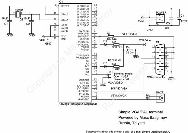
To prevent image distortion when receiving data via UART for VGA, it is advisable to conduct data exchange with the terminal approximately 300-600 microseconds after the vertical synchronization (VSYNC) signal. In a VGA system, the synchronization signals are crucial for...
This design modifies a high voltage flash for use with a low voltage camera by employing an optocoupler to provide electronic isolation between the camera's contacts and the high voltage. The flash can be triggered using the 6-volt supply...
The adapter is based on the FTDI USB/serial IC FT-232BM. It has been successfully tested with various transceivers and software, including the VX-7R (using VX-7R Commander), FT-8900 (via FTB-8900), FT-817 (with FT-817 Commander and Ham Radio Deluxe), and IC-706MkIIG...
Construct this circuit using any preferred method, ensuring that high voltage safety measures are strictly adhered to. Proper insulation is crucial, and bare conductors must be spaced at least 2mm apart to avoid arcing. This circuit functions as a...
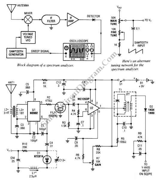
The circuit illustrated in the schematic diagram is a straightforward spectrum analyzer adapter circuit designed for oscilloscopes. This circuit can be utilized for scanning or analyzing signals. The spectrum analyzer adapter circuit is engineered to enhance the capabilities of an...