
Dvm Adapter For Pc Circuit

The voltage-to-frequency adapter functions by converting an input voltage signal into a corresponding frequency output. This is achieved through a series of electronic components that ensure accurate conversion while maintaining signal integrity. The signal conditioner enhances the quality of the output signal by filtering noise and amplifying the desired signal, thereby improving the overall performance of the circuit.
The protection circuit is designed to safeguard the adapter from potential overvoltage and overcurrent conditions that could arise from the connected game port. This is crucial in preventing damage to both the adapter and the PC. Typically, this protection circuit may include components such as diodes, fuses, or transient voltage suppressors that react to fault conditions.
The J2 connector serves as the interface between the adapter and the PC's game port, allowing for seamless communication and data transfer. The pin configuration of J2 must align with the game port specifications to ensure compatibility. The adapter's design may also consider the electrical characteristics of the game port, such as signal levels and impedance, to optimize performance.
For users looking to implement this circuit, reference materials provide guidance on the appropriate software to facilitate interaction with the adapter, ensuring that the voltage-to-frequency conversion can be effectively utilized in various applications. This integration of hardware and software enhances the functionality of the adapter, making it suitable for a range of projects within the realm of electronics and computer interfacing. The adapter consists of a voltage to frequency adapter with a signal conditioner and protection circuit. J2 connects to the game port of a PC. See reference listed for software for use with this circuit.
Related Circuits
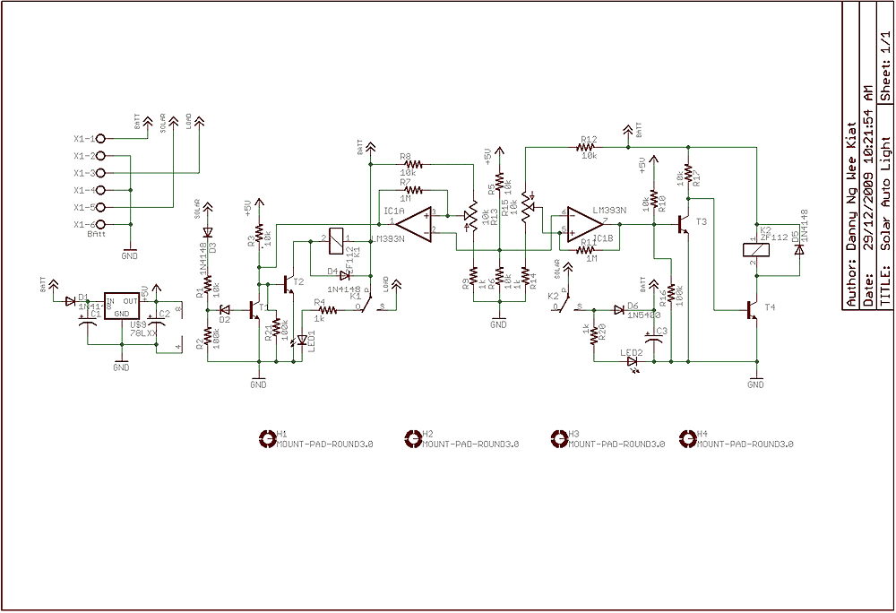
Few years back, I had been working on a project for solar auto lighting. The light will turn on when the solar panel voltage drop below a set point indicating that it is dark. The detection is done by...
This is a differentiator circuit. This circuit can be used to perform differential operations. There are two types of differentiators: the true differentiator and another type. A differentiator circuit is designed to output a voltage that is proportional to the...
If the transmitter stick-potentiometer delivers a voltage about 2 - 3 V, this circuit will be suitable. If you want to avoid using the battery cable (supplying Vcc for IC1 and -2), you can use a separate 5V supply...
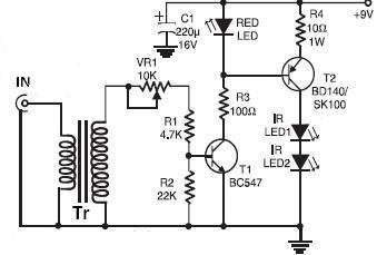
This wireless infrared (IR) headphones circuit project enables the transmission of audio signals through an infrared connection. The circuit consists of two main components: a transmitter and a receiver. Unlike radio frequency (RF) transmitters, both parts of this application...
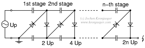
The Greinacher doubler circuit (a) transforms a grounded AC voltage (peak voltage Up) into symmetrical DC voltages of 1x Up each, thus producing 2x Up between outputs. If the input voltage is already symmetrical (e.g. as in an Obit),...
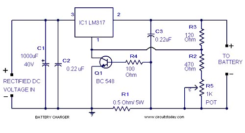
A simple lead-acid battery charger circuit with a diagram and schematic using the IC LM317, which provides the correct battery charging voltage. This lead-acid battery charger should be supplied with an input of 18 volts to the IC. The lead-acid...