
Commodore 64 Clock Circuits

The circuit described includes several key components that work together to produce and manage clock signals essential for various electronic applications. The crystal oscillator Y1 is fundamental in establishing the base frequency, providing a stable reference point for the system. The Dual Voltage Controlled Oscillator (U31) is crucial for generating the necessary clock signals, including the color clock and the DOT clock. By utilizing R27, adjustments can be made to fine-tune the output frequency, ensuring the precision required in applications such as video processing or timing circuits.
The frequency divider (U30) serves to reduce the frequency from the color clock to a more manageable 2 MHz, which can be used for different timing requirements within the system. The D flip-flop (U29) further divides this signal down to 1 MHz, demonstrating how multiple stages of frequency division can be implemented to achieve various operational needs.
U32's role as a Phase/Frequency Detector is critical in maintaining synchronization between the different clock signals. By comparing the outputs of the D flip-flop and the phase 0 clock, it ensures that any phase discrepancies are corrected, thereby maintaining the integrity of the clock signals. The output DC voltage from U32 serves as a feedback mechanism to adjust the frequency control input of the VCO, allowing for dynamic tracking of the clock signals.
Overall, this circuit configuration exemplifies a well-structured approach to clock signal generation and management, utilizing a combination of oscillators, dividers, and phase detectors to ensure precise timing in electronic systems.Crystal Y1 develops a 14. 31818MHz fundamental frequency clock signal. U31 is a Dual Voltage Controlled Oscillator. The output on pin 10 is a 14. 31818 MHz clock signal called the color clock. R27 can be adjusted to obtain exact output frequency. U30 is a frequency divider that outputs a 2MHz signal on pin 6. U29 is a D flip flop which outputs a 1MH z signal on pin 9. U32 is a Phase/Frequency Detector which compares the output of the U29 to the phase 0 clock, and outputs a dc voltage on pin 8 that is proportional to the phase difference between the inputs. The second half of the Dual Voltage Controller Oscillator U31 generates an 8. 1818MHz clock signal called the DOT Clock. The VIC IC divides the DOT clock by eight and outputs this as the phase 0 clock on pin 17. The output of the Phase/Frequency Detector is applied to the frequency control input pin 2 of U31. This causes tracking of the dot clock and the color clock because one input, pin 4 of U32, is the phase 0 clock which is derived from the dot clock, and the other pin 1 of U32, is derived from the color clock.
Crystal Y1 develops the fundamental 16Mhz clock signal. U31 is a Clock Generator IC that outputs the 8. 1818MHz DOT clock on pin 6, and the 14. 31818 MHz color clock on pin 8. 🔗 External reference
Related Circuits
The use of a quarter-wave parallel-wire line as a tuning unit has been discussed in the chapter on Short-Lines, where it was pointed out that these circuits have comparatively high Q even at higher frequencies. Their significant length (approximately...
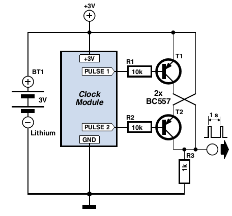
Many electronic projects require a timebase generator that is accurate to within a second. One method of achieving this is through the use of a microcontroller, quartz crystal, and appropriate software. However, a more cost-effective and straightforward approach is...
This month's project is based on the 4017 chip that was used in a previous project. It is advisable to review the fundamentals of the 4017 chip as presented in last month's project. The circuit has been modified slightly;...
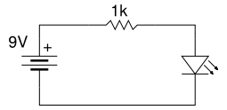
Beginner's Tutorial 1: Building a Circuit on Breadboard - how to build a simple and easy circuit on a breadboard for beginners in electronics. Learn to use an LED and a resistor. This tutorial serves as an introductory guide for...
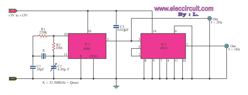
This is a standard digital clock circuit with a frequency of 1 Hz or 2 Hz. It can be utilized in a conventional clock circuit. The circuit comprises IC-4060 and IC-4013. The digital clock circuit operates by generating a precise...
This is a very simple project using a printed circuit board and 8 components. It will flash an ordinary 3mm or 5mm (1/8" or 1/4") LED at a rate of about one flash per second. This circuit works on...