
Negative Supply From Single Positive Supply

This circuit typically employs a charge pump or a voltage inverter configuration to create a negative voltage from the available positive supply. The design usually incorporates a switching element, such as a transistor or a dedicated IC, that alternately connects and disconnects the load to the supply. By utilizing capacitors in a specific arrangement, the circuit can effectively convert the positive voltage into a negative voltage.
For instance, a basic charge pump circuit might consist of a capacitor that is charged to the positive supply voltage and then switched to discharge into the output, creating a negative voltage potential. The switching can be accomplished using a diode or a MOSFET, depending on the specific requirements of the application, such as efficiency and response time.
Moreover, the circuit may include filtering components to smooth the output voltage and reduce ripple, ensuring that the negative voltage supplied to the op-amp is stable and reliable. Additionally, protection elements, such as diodes, may be integrated to prevent reverse polarity or overvoltage conditions that could damage the op-amp or other connected components.
In conclusion, this innovative circuit design provides a practical solution for utilizing op-amps in single-supply applications, significantly expanding their usability in various electronic systems.Opamps are very useful. But one of their major drawbacks is the requirement of a dual supply. This seriously limits their applications in fields where a dual supply is not affordable or not practicable. This circuit solves the problem to a certain extent. It provides a negative voltage from a single positive supply. 🔗 External reference
Related Circuits
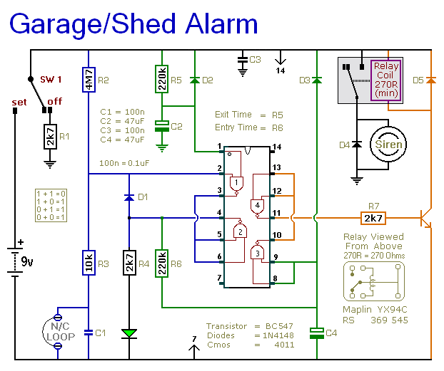
The following circuit illustrates a 9V power supply for a garage shed alarm circuit diagram. Features include a single-zone burglar alarm circuit that is used with the system. The 9V power supply circuit for the garage shed alarm is designed...

This design concept outlines a 12-V DC to 5-V DC (±5%) switched-mode power supply (SMPS). The supply utilizes a 12-V input derived from an array of four 3-V DC, 40-mA solar cells connected in series. The proposed switched-mode power supply...
This is an aerial current power supply with a continuously adjustable stabilized output ranging from 0 to 30VDC. The circuit also incorporates an electronic current limiter that effectively controls the output current from a few milliamperes (2 mA) to...
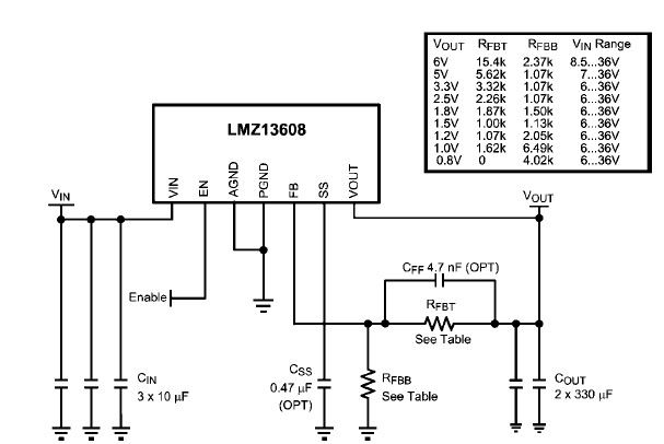
A simple, high-efficiency switching power supply circuit can be designed using the LMZ13608 8A regulator. This regulator offers very high efficiency and requires few external components. It supports a wide input voltage range of 6 to 36 volts and...
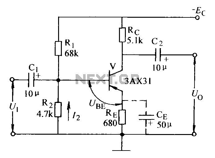
Current negative feedback voltage divider biased circuit diagram. The current negative feedback voltage divider biased circuit is a configuration commonly used in electronic amplifiers to stabilize the operating point and improve linearity. This circuit typically consists of an amplifier, a...
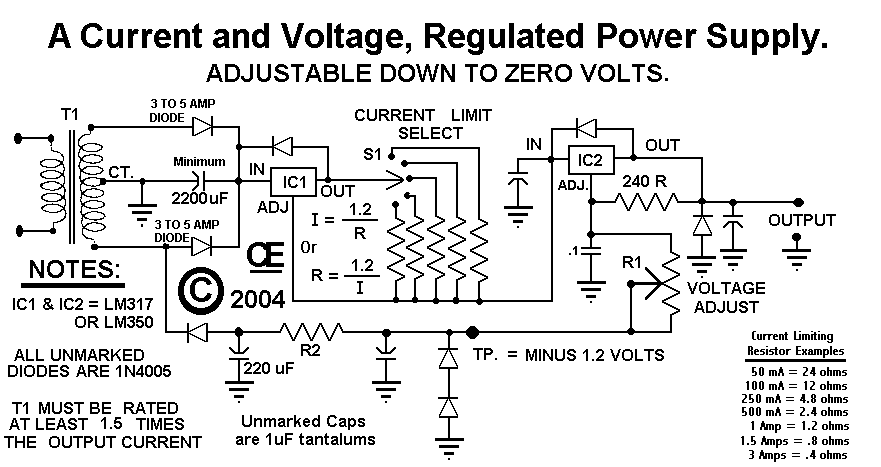
This circuit employs a rotary switch to select various current ranges, as using a potentiometer is not practical for lower resistance and high current ranges. However, a potentiometer can be utilized for lower current ranges, with the lowest switch...