
Common intermediate frequency amplifier circuit having a circuit and on the radio

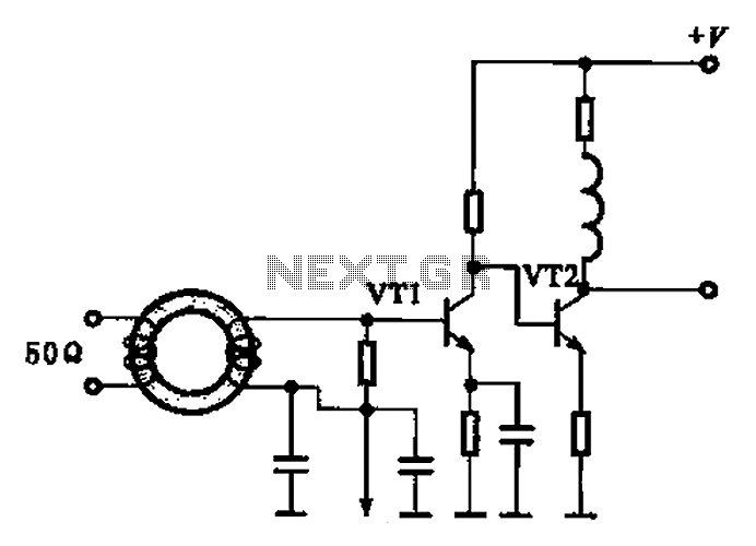
The intermediate frequency (IF) amplifier circuit is essential in radio communication systems, where it amplifies signals after the initial frequency conversion. The circuit employs a transistor configuration, specifically the 3DG19, which operates at a supply voltage of 6V. The transistor's role is to amplify the incoming IF signal while maintaining linearity and minimizing distortion.
The resistors in the circuit are carefully selected to set the biasing conditions for the transistor. R1, with a value of 50 kΩ, is connected to the base of the transistor, providing the necessary base current for operation. R2, valued at 10 kΩ, is used for feedback, enhancing the stability of the amplifier. The emitter resistor Re, at 1 kΩ, plays a critical role in stabilizing the operating point of the transistor against variations in temperature and supply voltage.
Capacitance values are also crucial in determining the frequency response of the amplifier. C1, which is 0.01 μF, acts as a coupling capacitor, allowing AC signals to pass while blocking DC components. C2, with a value of 200 pF, and C3, at 6 pF, are used for bypassing and filtering, ensuring that unwanted high-frequency noise does not affect the amplifier's performance.
The simplicity of this circuit design allows for easy implementation while providing robust performance characteristics. The stability of the IF amplifier is further ensured by the careful selection of component values, which allows it to operate effectively in various conditions. Overall, this intermediate frequency amplifier circuit is a reliable solution for enhancing signal clarity in radio applications. Common intermediate frequency amplifier circuit having a circuit and on the radio as shown in FIG. Component Parameters Reference values are as follows: 1) transistors: VT1 to 3DG19, Vcc 6V. 2) Resistance: Rhl - 50kCZ, Rh2 lOkfl, Re, a lkfl. 3) Capacitance: cl-G o OlyF. Pakistan 200pF, CN 6pF. And having an intermediate frequency amplifier circuit and due to the addition circuit, to ensure stable operation of the IF amplifier, and the circuit is simple, is a kind of good performance amplifier.
Related Circuits
This article presents a high reliability 1200V High Voltage Integrated Circuit (1200V HVIC) for half bridge driver applications, aimed at reducing the IC's supply current by approximately 50%. The 1200V High Voltage Integrated Circuit (HVIC) is designed specifically for half-bridge...
A simple variable frequency oscillator utilizing a 555 timer IC to generate a square wave frequency that can be adjusted using a potentiometer. The circuit operates primarily on the principles of astable multivibrator configuration using the 555 timer IC, which...
A broadband high-frequency amplifying circuit is primarily composed of a high-frequency matching transformer and an amplifying transistor. This circuit is designed to handle large high-frequency signals. The input of the amplifier circuit utilizes a matching transformer to ensure that...
A board design intended for measuring a load cell has been identified with a system accuracy fault traced to the amplifier integrated circuit (IC). The output of the amplifier IC changes when the board is twisted, yielding +80mV when...
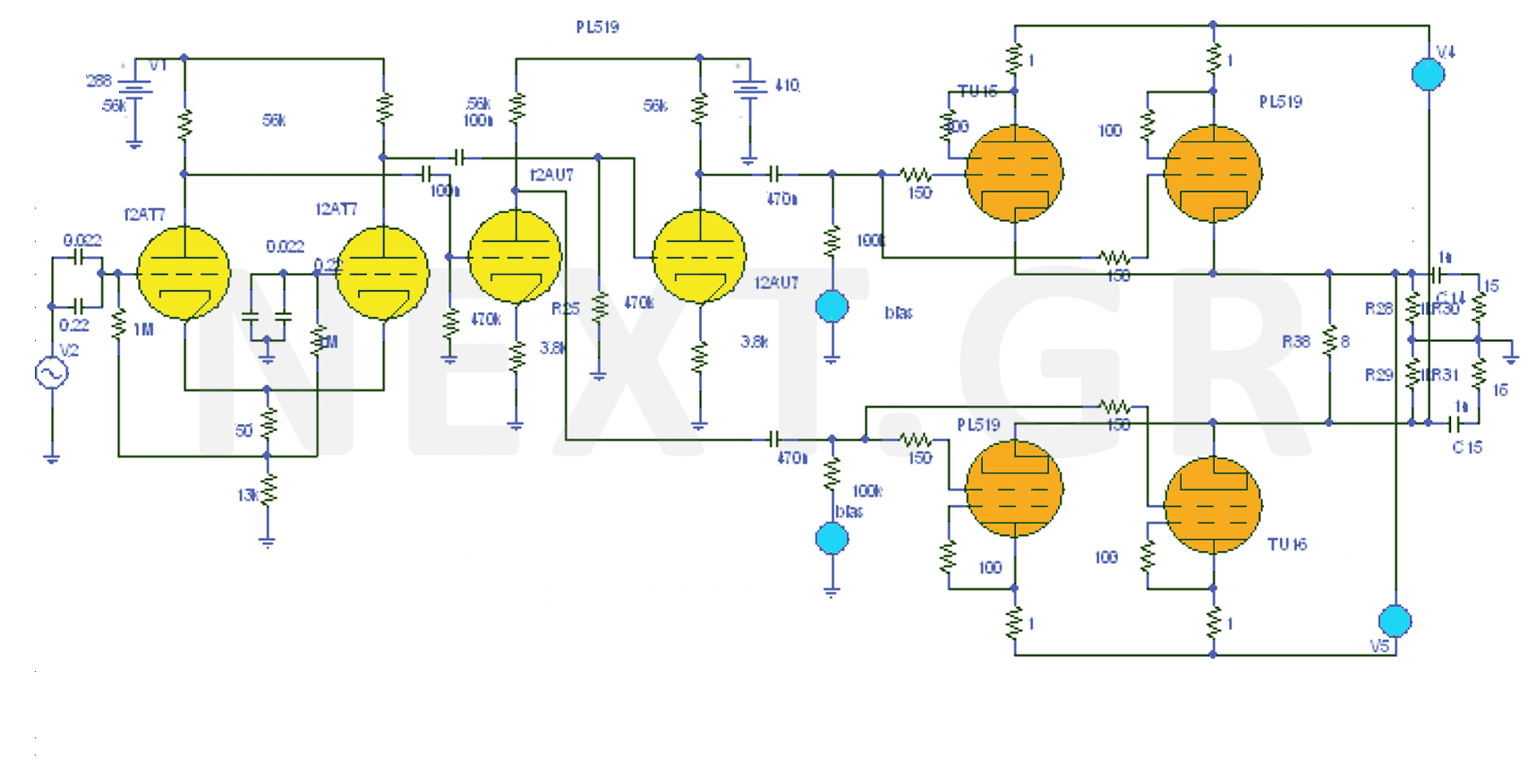
The design of the 40W Valve Amplifier is illustrated in the accompanying figure. Valve amplifiers are characterized by a prominent presence of second and third harmonics, sometimes accompanied by fourth and fifth harmonics, but always with a wider bandwidth....
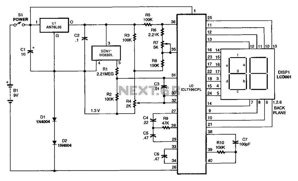
The output DC voltage of sensor SEN1 changes linearly in response to variations in relative humidity. This DC voltage is routed through resistors R1 and R2 to the analog-to-digital (A/D) converter chip U2. Resistor R4 is connected to ground,...