
230 Volt AC To Inverter SwitchingCircuit

The presented circuit diagram effectively integrates a switching mechanism that transitions between AC mains power and inverter power. The use of transistors BC558 and BC548, which are NPN and PNP types, respectively, allows for efficient control of the relay. The relay serves as a crucial component, enabling the switching between two power sources based on the operational state of the circuit.
In this configuration, when the AC mains power is available, the positive voltage at the base of Q1 turns it ON, allowing current to flow through the relay coil, which activates the relay and connects the load to the AC source. This ensures that the load receives the required voltage for normal operation. Conversely, when the AC mains power is interrupted, the voltage at the base of Q1 drops to ground, causing it to turn OFF. At this point, the base of Q2 receives a positive voltage, turning it ON and energizing the relay in the opposite configuration. This action disconnects the load from the AC source and connects it to the inverter output, allowing the load to continue functioning without interruption.
The overall design is suitable for applications requiring a seamless transition between AC and inverter power, such as in uninterruptible power supplies (UPS) or backup power systems. The choice of components, including the relay's rating and the transistor specifications, should be carefully considered to ensure the circuit can handle the expected load and operate reliably under different conditions. Proper heat dissipation techniques for the transistors and relay should also be implemented to maintain circuit integrity and performance over time.Before three weeks i am introduced inverter circuit diagram but the circuit not included ac to inverter switching part so today i introducing a 230 Volt Ac to inverer switching circuit diagram. Circuit showing a inverter switching. Here i have used bc 558, BC 548 and a relay for making this circuit. 230 volt connected to the base of the transis tor Q1. When the power is ON positive volt coming to the base of the transistor so the relay circuit is open and load working in 230 V AC. When the power is OFF ground voltage coming to the base of the transistor so the Base of the Q2 is positive there for the relay circuit closed and load working in inverter input.
Part list and applications are showing below. Link 🔗 External reference
Related Circuits
This is a voltage multiplier circuit. The first circuit is used to double a square wave (of any amplitude). However, there is a drawback of approximately 2V losses in the base-emitter. A voltage multiplier circuit is designed to increase the...
Power line fluctuations and cut-offs can damage electrical appliances connected to the line, particularly domestic appliances such as refrigerators and air conditioners. Operating a refrigerator on low voltage can lead to excessive current flowing through the motor, resulting in...
The DVM-to-temperature adapter is constructed around a single integrated circuit (IC), the National LM10. This micropower IC features a stable 0.2 V reference, a reference amplifier, and a general-purpose operational amplifier. The circuit is designed to operate within a...
The MAX6499 includes undervoltage and overvoltage comparators for window detection. When the monitored voltage is within the selected window, the GATE is enabled. The MAX6499 is a precision voltage monitoring device designed to detect both undervoltage and overvoltage conditions within...
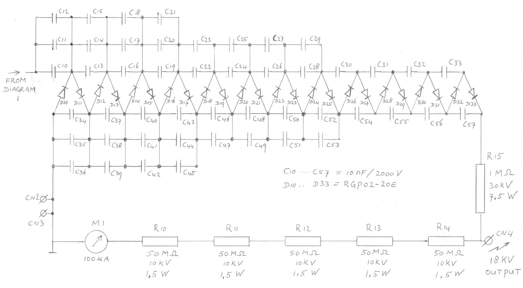
Each subsequent stage adds 1700 volts, resulting in more than 20 kV with 12 stages. However, this voltage can only be achieved when the output of the cascade is unloaded. The described circuit appears to be a high-voltage cascade generator,...
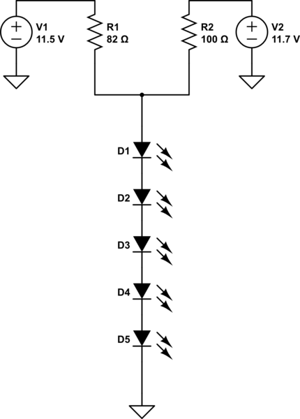
A series of LEDs is intended to display at two brightness levels, and there is uncertainty regarding the proper wiring. This setup is for additional running lights and brake lights on a bicycle. When using the series LED calculator,...