
Common non-sinusoidal oscillator circuit waveform pulse wave oscillator blocking oscillator transformer

The common non-sinusoidal oscillator circuit is designed to generate pulse waveforms, which are characterized by their square or rectangular shape. These oscillators are essential in various electronic applications, including clock generation, signal modulation, and timing circuits. The pulse wave oscillator operates by utilizing a feedback mechanism that allows the circuit to switch between high and low states rapidly, resulting in a periodic output waveform.
The frequency of the pulse waveform generated by a blocking oscillator can be determined using specific formulas that take into account the values of the circuit components, such as resistors, capacitors, and inductors. In a typical blocking oscillator configuration, a transformer is employed to provide feedback to the transistor or active device, enabling it to oscillate. The frequency of oscillation is influenced by the inductance of the transformer and the capacitance in the circuit.
The output waveform of a pulse wave oscillator can be visualized as a series of sharp transitions between the high and low voltage levels, with a duty cycle that can be adjusted based on the circuit design. The duty cycle is defined as the ratio of the time the output is in the high state to the total period of the waveform. This characteristic makes pulse wave oscillators particularly useful in applications where precise timing and control of signal duration are required.
In summary, the common non-sinusoidal oscillator circuit, specifically the pulse wave oscillator and blocking oscillator transformer configuration, is a fundamental component in electronic design, providing essential timing and waveform generation capabilities. Understanding the underlying principles and formulas governing these circuits is crucial for engineers working in the field of electronics. Common non-sinusoidal oscillator circuit, waveform and frequency formula - pulse wave oscillator - blocking oscillator transformer
Related Circuits
Here is an updated schematic featuring the RF Solutions receiver along with several minor additions. The design includes additional circuitry to manage the signals effectively. The updated schematic incorporates an RF Solutions receiver, which is essential for receiving radio frequency...
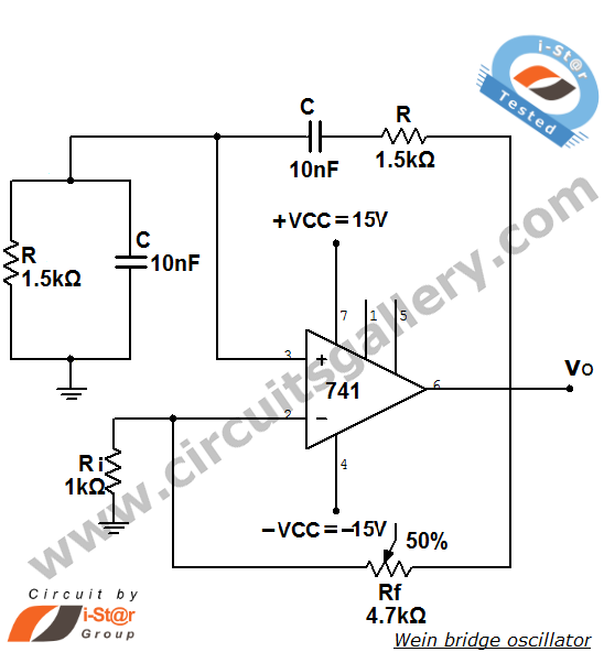
The Wien bridge oscillator is a high-stability audio frequency sine wave oscillator known for its simplicity. An oscillator is defined as a circuit that generates periodic electric signals, such as sine waves or square waves. Applications of oscillators include...
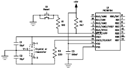
The following file contains detailed information about the design of a basic clock oscillator circuit diagram. Included in this file is information about selecting the components. The clock oscillator circuit is a fundamental component in various electronic systems, providing a...
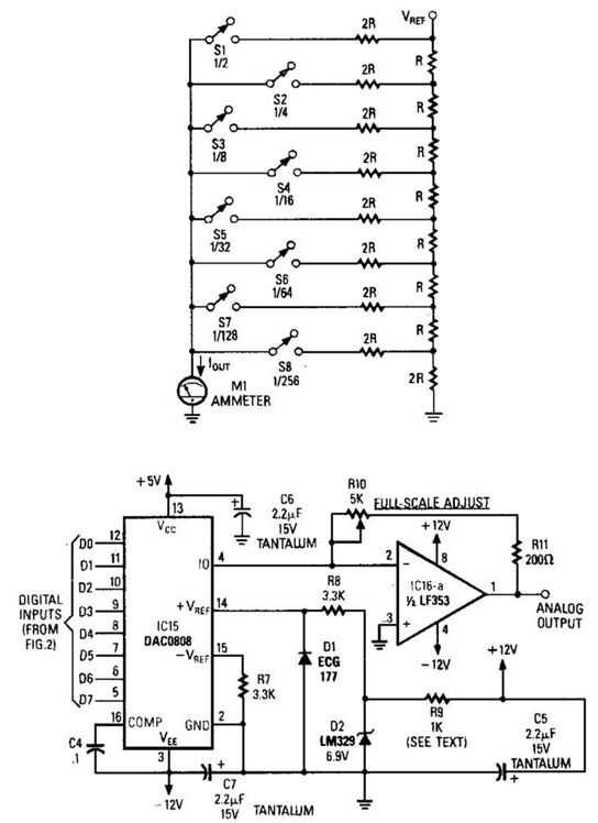
Figure A illustrates an R/2R resistor ladder. Each closed switch increases the current output. A basic channel A/D converter is depicted in Figure B. The voltage reference (D2) is shared among all channels, while the value of the dropping...
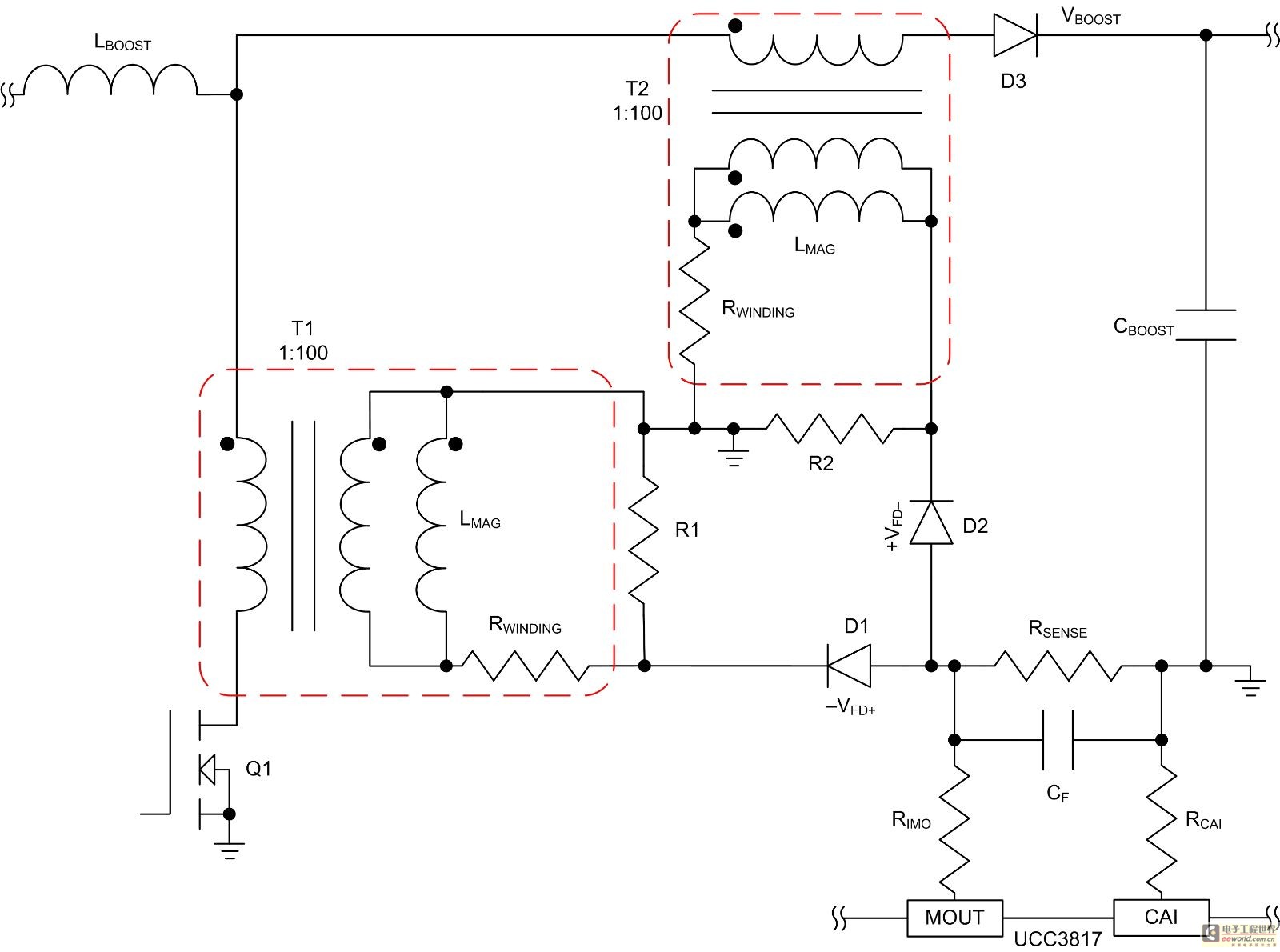
Mode control of the average current (CMC) is necessary to regulate the overall waveform of electric current during the rebuilding cycle. This text recommends selecting specific parameters related to the voltage transformer and outlines steps for designing a circuit...
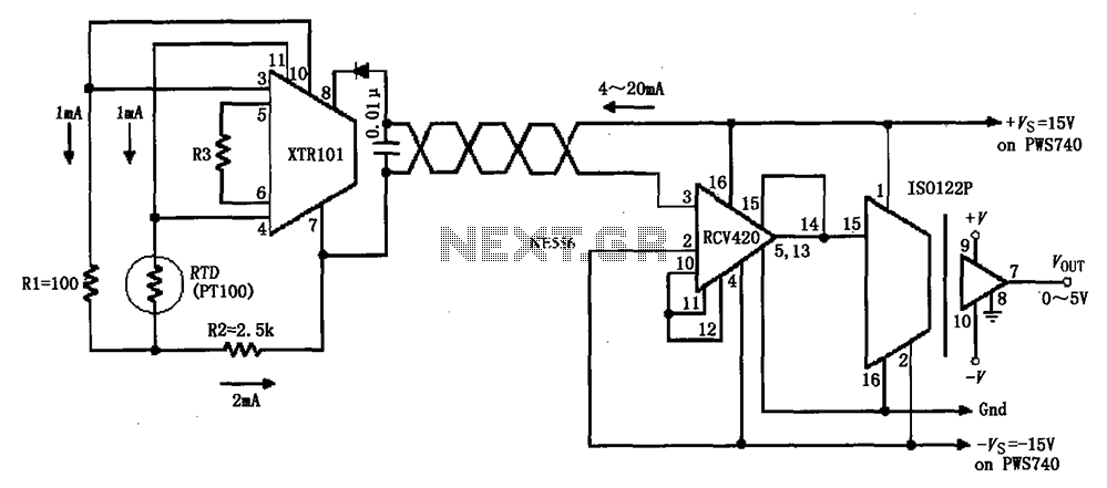
The circuit comprises an isolated RTD loop current configuration utilizing the XTR101 for transmitting loop current and the RCV420 for receiving it. The instrumentation amplifier detects changes in temperature via a resistance temperature detector (RTD), converting these changes into...