
Clock Oscillator BasicCircuit from Sirius microSystem

The clock oscillator circuit is a fundamental component in various electronic systems, providing a stable clock signal for timing applications. The design typically includes a few essential components: an oscillator, a capacitor, and a resistor. The oscillator can be a transistor-based configuration or an integrated circuit (IC) like the 555 timer.
In designing the circuit, the selection of the oscillator type is crucial. For low-frequency applications, a simple RC (resistor-capacitor) oscillator may suffice, while higher frequencies might require more sophisticated arrangements, such as a crystal oscillator, which offers enhanced stability and precision.
The capacitor in the circuit plays a significant role in determining the frequency of oscillation. The value of the capacitor, in conjunction with the resistor, sets the time constant, which directly influences the oscillation frequency. The relationship can be expressed using the formula f = 1/(2πRC), where f is the frequency, R is the resistance, and C is the capacitance.
Additionally, the power supply voltage must be carefully considered to ensure that all components operate within their specified limits. Proper decoupling capacitors may also be added to filter out noise and ensure stable operation.
The output of the clock oscillator can be used to drive other digital circuits, such as flip-flops, counters, or microcontrollers, providing them with a reliable timing source. The design should also include provisions for adjusting the output frequency, which can be achieved through variable resistors or capacitors, depending on the application requirements.
Overall, the clock oscillator circuit is essential for synchronizing operations in digital electronics, and careful attention to component selection and circuit design will ensure optimal performance.The following file contains detail info about design of Clock Oscillator Basic Circuit Diagram. Included in this file information about: selecting the.. 🔗 External reference
Related Circuits
Opamps are very useful. But one of their major drawbacks is the requirement of a dual supply. This seriously limits their applications in fields where a dual supply is not affordable or not practicable. This circuit solves the problem...
The idea to produce a standard TV PAL signal using a SVGA graphics card was born a few years ago, where cheap graphics cards with TV output were still not available. To achieve a CCIR conform TV signal with...
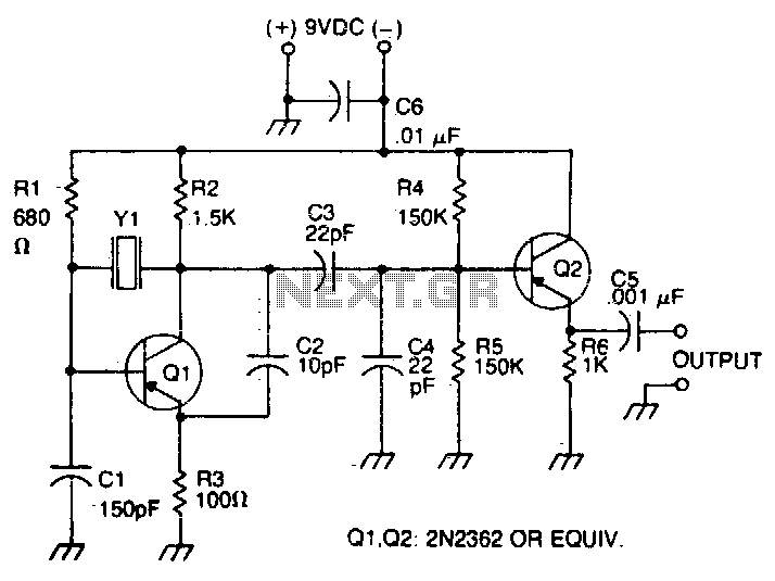
The oscillator transistor is Q1, and the crystal is placed between the collector and base. Feedback is improved by the use of the collector-emitter capacitor C2. Transistor Q2 is used as an output buffer. The circuit described features an oscillator...
This is a programmable clock timer circuit that utilizes individual LEDs to display hours and minutes. Twelve LEDs can be arranged in a circle to represent the twelve hours of a clock face, while an additional twelve LEDs can...
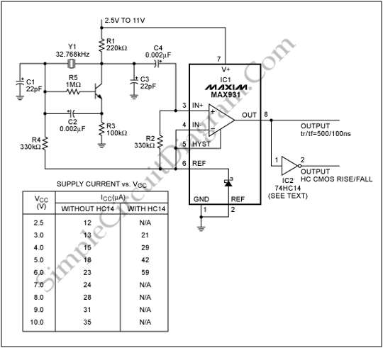
To generate a system clock or auxiliary sleep clock in microcontrollers (µCs) and low-power instruments, a 32 kHz oscillator is commonly utilized. This oscillator typically employs a CMOS inverter. A 32 kHz oscillator is essential for various timing functions in...
A couple of motors were salvaged from an old printer, and there is uncertainty regarding how to connect them to a breadboard and subsequently to a Raspberry Pi. A cobbler kit for the Raspberry Pi is available for this...