
demystifying use of table pointer in

To configure the microcontroller for SPWM, the ANSEL register is set to 0 to designate the ADC-associated pins as digital, as the ADC functionality is unnecessary for this application. This configuration allows the multiplexed pins to serve as digital I/O lines. Similarly, the CMCON0 register is set to 7, disabling the comparator functionality. Initially, PORTC bits 0 to 5 are configured as inputs. The CCP1CON register is set to 0x4C, which activates PWM mode with P1A, P1B, P1C, and P1D configured as active-high outputs. Timer 2 is enabled, and a polling mechanism checks for Timer 2 overflow. Upon overflow, the interrupt flag is cleared, and PORTC bits are set as output pins. Timer 2 interrupts, global interrupts, and peripheral interrupts are then enabled, allowing the program to enter an infinite loop, awaiting interrupt events.
With PR2 set to 249, the timer generates an interrupt every 62.5 microseconds. During each interrupt, the interrupt service routine is executed. In the main function, the SET_FREQ variable is assigned a value of 410, which determines the output frequency of the sine wave, specifically set to 50Hz. Within the interrupt routine, the TBL_POINTER_NEW variable is updated every 62.5 microseconds, incrementing by 410 each time. Initially, TBL_POINTER_NEW is set to 0, and its value increases with each interrupt: 410 after the first, 820 after the second, and so forth. After 159 interrupts, TBL_POINTER_NEW reaches a value of 65190, allowing for the continuous generation of the desired sine wave output. This systematic approach ensures that the SPWM implementation is efficient and adaptable to varying output frequencies and sine table sizes.Sinusoidal pulse width modulation (SPWM). I`ve discussed about how to generate the sine table, how to implement it, how to practically generate the SPWM signals (with example code) and also how to implement feedback with simple sine table manipulation with table pointer instead of complex PID control. All these methods have one thing in common regarding the implementation - use of the sine table and its control with the table pointer. Whether you use or implement feedback or not, the table pointer is used to access and retrieve values from the sine table. It took quite a while for me to understand exactly how the table pointer works in this case to retrieve data from the sine table and feed it to the PWM module and generate the required output 50Hz frequency (you can use any frequency but my requirement is 50Hz).
I had come across the method and its explanation when coding for the dsPIC33 microcontroller while I was attempting to make a sine wave inverter using the dsPIC33. After a lot of research and thinking, I could finally implement it for PIC16. While many have seen my posted codes and explanations regarding sinusoidal pulse width modulation (SPWM), some people have requested me to explain how the table pointer in the interrupt works.
Remembering my difficult experience with this, I decided to write up this article to help all of you who are struggling with this to help clear your doubts and make you understand exactly how it works so that one can implement SPWM with a sine table with any number of table values and for any desired output frequency. Let`s take a look at the code line by line. And I`ll explain it all. Keep in mind that the target microcontroller is a PIC16F684 running off an oscillator frequency of 16MHz.
So, if you`re attempting to port the code to any other microcontroller keep in mind that the registers will/may be different from those in the PIC16F684. Now, back to the software side of things. The registers responsible for the automatic updating of the duty cycle are SET_FREQ, TBL_POINTER_SHIFT, TBL_POINTER_NEW, TBL_POINTER_OLD and DUTY_CYCLE.
So, I`ll get to this a little later. Let me deal with the rest first. Setting ANSEL to 0 selects the ADC-associated pins as digital and this is done since the ADC isn`t required for this program, and this frees up the pins multiplexed to the ADC so that they can be used as digital IO lines. Setting CMCON0 to 7 does the same thing, just for the comparator instead of for the ADC. PORTC bits 0 to 5 are all made input at first. CCP1CON is set to 0x4C. This sets the ECCP mode to PWM Mode with P1A, P1B, P1C and P1D set active-high. Timer 2 is turned on and a polling check is done to check if Timer 2 has overflowed or not. When Timer 2 overflows, the interrupt flag is cleared and PORTC bits are selected as output pins. Timer 2 interrupt, global interrupt and peripheral interrupt are enabled. Now the program just loops in the infinite endless while loop. So, the program now just does nothing but execute the interrupt when it occurs. Since PR2=249, the time period is 62. 5us. I assume you can do the math. So, an interrupt occurs every 62. 5us. Now on to the main part of this code the interrupt. Every 62. 5us the interrupt service routine is entered (if you think of it like that in terms of program flow ) and executed.
In the main() function, I had assigned the value of 410 to SET_FREQ. SET_FREQ determines the output frequency of the sine wave, which in our case here is 50Hz. You`ll soon see how. In the interrupt, the variable TBL_POINTER_NEW is updated every 62. 5us it is increased by 410. TBL_POINTER_NEW is a 16-bit variable and at the beginning of program execution has a value of 0. So, after the first interrupt it holds 410, after the second interrupt 820, after the third 1230 and so on. After 159 interrupts, TBL_POINTER_NEW holds 65190. So, at the ne 🔗 External reference
Related Circuits
Function: to trigger a device or operate in free-running mode. Components: Battery, Charger, Battery Connector, Capacitor, Integrated Circuit (IC), Resistor VR1-10K, Resistor R1-1K, Resistor R2. The described circuit functions either to trigger a connected device or to operate in a...
Electronics tutorial about multivibrators, including monostable multivibrator circuits, astable multivibrators, bistable oscillators, and clocks. Multivibrators are essential electronic circuits that generate specific output waveforms based on their configuration. They are classified into three primary types: monostable, astable, and bistable multivibrators....
The PE014A12 relay from Tyco Electronics features a single coil that requires a positive voltage to activate and a negative voltage to deactivate. The PE014A12 relay is a single-coil electromagnetic relay designed for applications requiring a simple on/off switching mechanism....
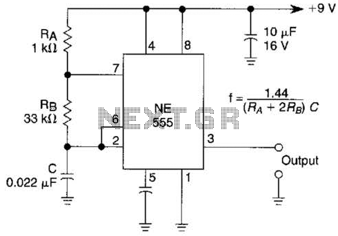
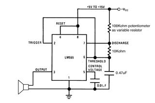
An astable multivibrator based on the 555 timer is presented. The frequency is approximately 975 Hz, determined by the values of RB and C. The astable multivibrator configuration using the 555 timer is a popular circuit for generating square wave...
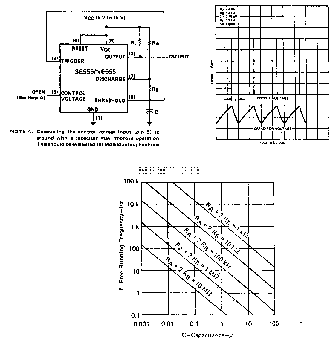
The capacitor C will charge through resistors Ra and Rb, and then discharge through resistor Rb only. The duty cycle may be controlled by the values of Ra and Rb. In this circuit configuration, a capacitor (C) is utilized to...
Setting the 555 timer in astable mode results in a continuous series of output pulses. The 555 timer IC, when configured in astable mode, operates as an oscillator, generating a square wave output. This configuration does not require any...