
DC to AC Converter 12V to 220V Voltage Converter

The circuit design of this DC to AC converter primarily revolves around the CMOS 4047 integrated circuit, which functions as an astable multivibrator. This configuration generates a square wave output, which is essential for the conversion process. The output frequency can typically be adjusted based on the external resistors and capacitors connected to the IC, allowing for flexibility in the output waveform.
The conversion begins with the input of 12V DC, which is supplied to the CMOS 4047. The IC generates a square wave at a frequency that can be set between 50Hz to 60Hz, depending on the application requirements. The square wave output is then fed into a transformer, which steps up the voltage from 12V to 220V AC. The transformer must be rated appropriately for the power requirements of the load that will be connected to the output.
Additionally, the circuit may include components such as diodes for rectification, capacitors for smoothing the output, and possibly a filter to reduce electromagnetic interference. It is crucial to ensure that all components are rated for the voltages and currents they will encounter during operation to maintain safety and reliability.
In summary, this DIY converter is a practical solution for applications requiring a 220V AC supply from a 12V DC source, with the CMOS 4047 providing an efficient and adjustable means of generating the necessary AC waveform. Proper attention to component selection and circuit design will ensure effective performance and safety in operation.This DIY 12V to 220V DC to AC converter is built with CMOS 4047 that is the main component of this small voltage converter that transforms a 12VDC into 220.. 🔗 External reference
Related Circuits
The voltage to frequency converter (V/FC - VCO) circuit consists of a UJT (uni-junction transistor) oscillator in which the timing charge capacitor C2 is utilized. The voltage to frequency converter circuit operates by converting an input voltage into an output...
This circuit is a simple design that outputs a voltage higher than the input. It can be used to power 12V or 9V devices from a 6V system or to operate 6V devices from a 1.5V battery. The circuit...
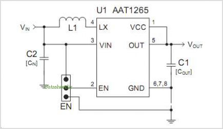
The AAT1275 evaluation board serves as a platform for testing and evaluating the AAT1275 switching boost converter equipped with a USB power switch. This evaluation board showcases the recommended size and placement of external components to achieve 5V output...
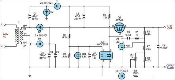
The circuit is a MOSFET-based linear voltage regulator capable of a voltage drop as low as 60mV at 1A. It utilizes a 15V-0-15V transformer and an IRF540 N-channel MOSFET (Q1) to provide a regulated 12V output. The gate drive...
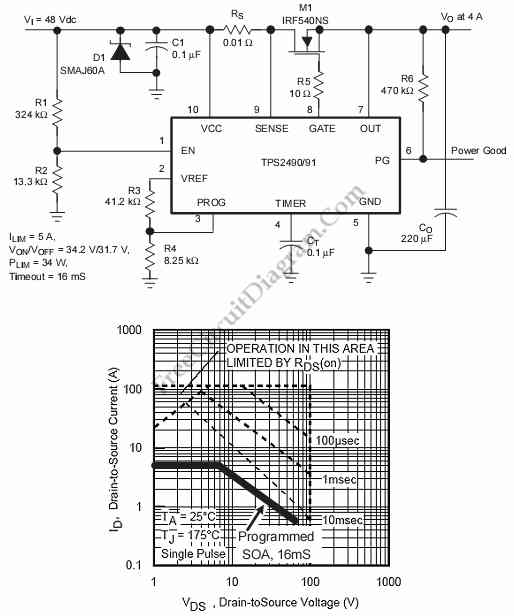
This is a positive high-voltage hot swap controller circuit with a power limiter. This circuit utilizes the TPS2491 or TPS2490, as both of them have specific features. The positive high-voltage hot swap controller circuit is designed to safely connect and...
First circuit is for connecting VGA card to video projector or a monitor which accept VGA card frequencies and has RGB + Composite sync input. This circuit has been successfully used with Electrohome Projection Systems ECP 4100 data and...