
COMPLETE 3 W 400 CPS SERVO AMPLIFIER

The circuit described is designed for driving a 3W servo motor, which requires careful consideration of its operational environment. The ability to function effectively in extreme temperatures, from -55°F to 125°F, necessitates the use of high-temperature-rated components, particularly capacitors. These components must be selected to ensure reliability and performance under these conditions.
The gain adjustment feature allows for fine-tuning of the circuit's output, enhancing its versatility in various applications. By adjusting the RF component within the driver circuit, the gain can be set anywhere between 20,000 to 80,000 amperes per ampere. This wide range of gain adjustment makes the circuit suitable for different servo motor specifications and loads, enabling it to adapt to various operational requirements.
Moreover, the stability of gain across the operating temperature range is crucial for consistent performance. The specification that gain varies by less than 10% indicates that the circuit maintains its efficiency and effectiveness, which is essential for applications where precision control of the servo motor is required.
In practical applications, this circuit would be implemented in environments such as aerospace, automotive, or industrial automation, where robust performance under extreme conditions is necessary. The design must also consider factors such as power supply requirements, heat dissipation mechanisms, and protection against voltage spikes to ensure long-term reliability and operational integrity.Is capable of driving 3. w servo motor in ambient of -55 to 125ƒ, if capacitors for 125ƒ are used. Gain can be adjusted over range of 20, 000 to 80, 000 amp per amp by adjusting RF in driver circuit. Gain varies less thon 10% over operating temperature range. -"Transistor Manual, " Seventh Edition, General Electric Co. , 1964, p 225. 🔗 External reference
Related Circuits
The TDA8581(T) from Philips Semiconductors is a 1-watt Bridge Tied Load (BTL) audio power amplifier capable of delivering 1 watt of output power into an 8-ohm load at a total harmonic distortion (THD) of 10% while using a 5V...
Although many album titles that were once available on vinyl are gradually being released as CDs, not all are accessible. There may be valuable records in a collection that one wishes to convert to CDs. Preserving a CD is...
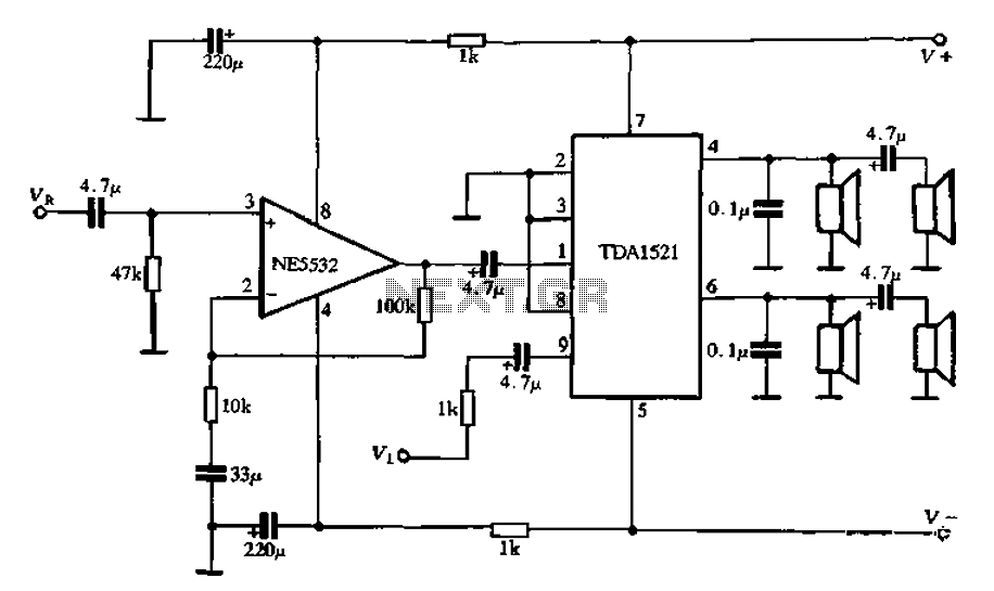
Active speaker with amplifier circuit TDA1521 and NE5532, featuring dual-channel input and dual-channel output. The active speaker circuit utilizes the TDA1521 integrated circuit, which serves as the power amplifier. This IC is designed for high-efficiency amplification, providing a robust output suitable...
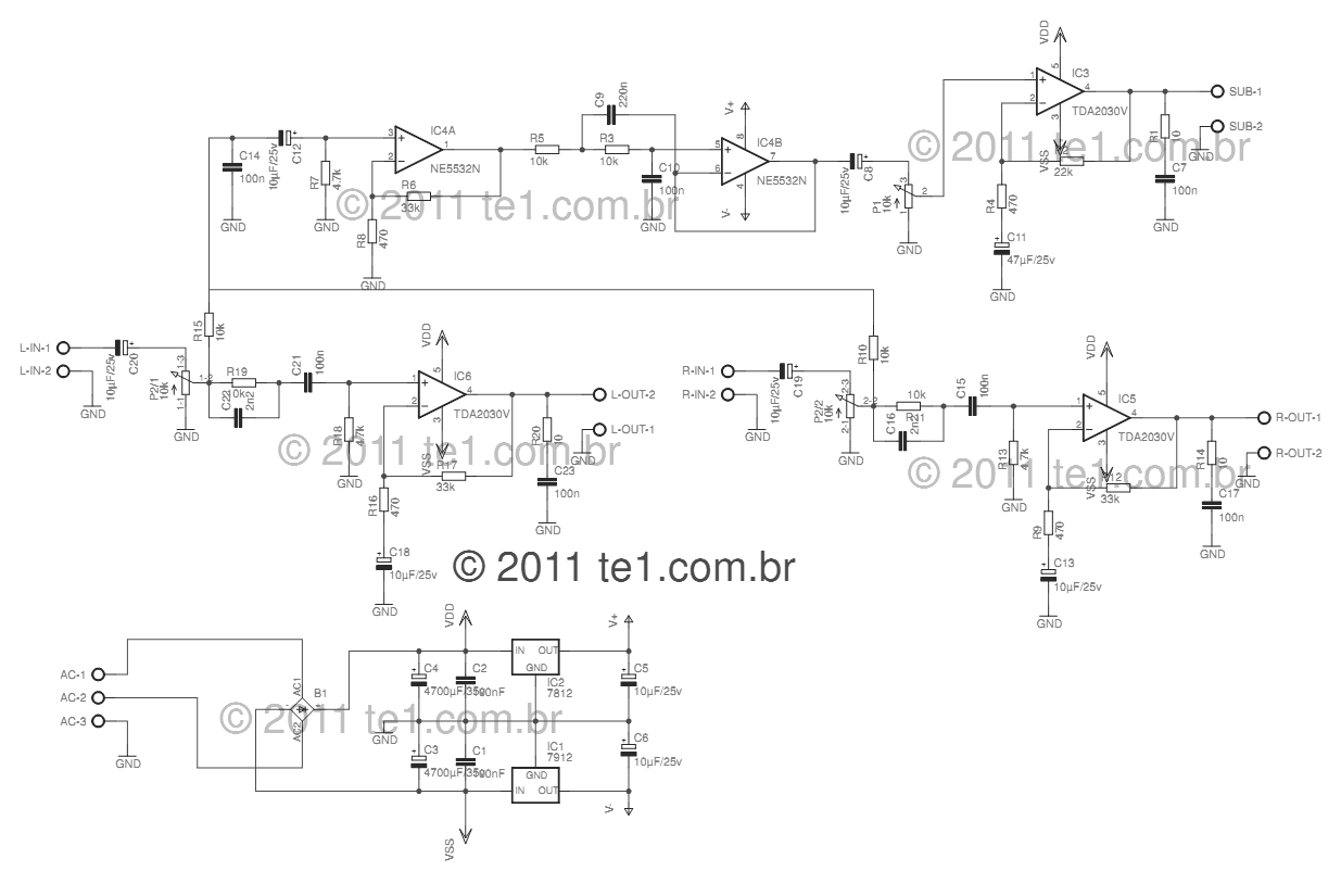
This circuit is a complete application for a 2.1 amplifier system, featuring two satellite speakers for TDA and one subwoofer. It is commonly used in commercial applications to enhance the audio output of computers using a stereo amplifier along...
This reference design demonstrates the MAX98400 Class D audio amplifier in a stereo audio docking station application. The demo box is a powered speaker dock that drives a speaker system consisting of 2-inch satellite speakers and a 5-inch subwoofer. The...
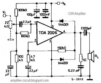
The power amplifier IC TDA2006 provides high output current and has very low harmonic and cross-over distortion. Furthermore, the device incorporates an original (and patented) short circuit protection system that automatically limits the dissipated power to keep the working...