
Component Signature for Oscilloscope

The described circuit operates as a basic component tester utilizing an oscilloscope to visualize the response of various electronic components. The test signal, derived from the mains, is a sine wave at either 50Hz or 60Hz, which is standard in most electrical systems. The Device Under Test (DUT) is connected to the circuit, and the oscilloscope's display behavior changes based on the connection state of the DUT.
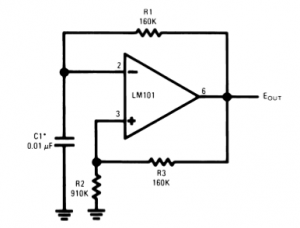
When the DUT terminals are open, there is no voltage across resistor R1, resulting in the oscilloscope displaying a horizontal line on the X-axis, representing the full test signal voltage. Conversely, when the DUT terminals are shorted, the voltage across R1 becomes significant, causing the oscilloscope to display a vertical line on the Y-axis. This behavior illustrates the basic operation of the circuit, where R1 serves to limit the current flowing through the DUT to prevent damage.
The circuit can be used to test various components such as diodes, capacitors, inductors, and resistors. Each component will produce a unique pattern on the oscilloscope, allowing for easy identification and analysis. For instance, a diode will show a characteristic response distinct from that of a capacitor or an inductor. The circuit's design allows for a mixture of X and Y axis signals when testing components that are neither open nor short-circuited, producing recognizable signatures.
The construction of the tester is straightforward and does not require a printed circuit board (PCB). However, careful attention must be paid to the switching mechanism, as incorrect configurations can lead to erroneous results. The circuit diagram provides guidance on the proper placement of components and switch positions, ensuring accurate operation.
The transformer used in this circuit can vary in size, but it is essential to select a transformer that can handle a maximum current drain of 20mA. A multi-tapped transformer with a primary voltage of 30V is recommended, where the taps can be utilized to provide various secondary voltages. The common tap is connected to the 30V output, while the 24V tap is used for a 6V output, and the 0V tap provides the full 30V. The RMS voltages should be noted, as they will influence the peak voltages observed during testing.
In summary, this circuit serves as a versatile and practical tool for testing electronic components, providing visual feedback through an oscilloscope and allowing for the analysis of their electrical characteristics.The general (and very basic) principle of operation is shown in Figure 1. The test signal is simply derived from the mains, and is a sinewave at 50 or 60Hz. In most locations, the sinewave will be distorted, but this barely matters. With nothing connected to the DUT (Device Under Test) terminals, the oscilloscope simply displays a horizontal line. This represents voltage, and is applied to the X axis of the oscilloscope. If the DUT terminals are shorted, the display changes to a vertical line (Y axis). This behaviour is easily explained by looking at Figure 1. With the terminals open, there is no voltage across R1, so nothing is applied to the Y axis of the oscilloscope. The full voltage is applied to the X axis, and produces a horizontal line. R1 is selected to limit the current through the DUT to a safe value. Now, if we short the test leads, the signal to the X axis is shorted out, and the voltage from the transformer is now across R1, and is directed to the Y axis resulting in a vertical line.
When any component that is not open or short-circuited is probed, there will be a mixture of X and Y axis signals applied to the CRO, and a distinctive pattern is produced. Diodes, inductors, capacitors, transistor junctions and resistors all provide a unique signature, and any mixture of components will produce a result that is easily recognised.
The tester is easy to build, and no PCB is needed. Although construction is somewhat fiddly because of the switching, it is very straightforward. The switching is easy to get wrong though, so refer to the circuit diagram and make sure that everything is where it should be. All switch positions are shown on the diagram ... both voltage and current switches are in the 'Low' position. The transformer can be any size you have available or can find - the current drain is no more than 20mA.
As shown, a 30V multi-tapped transformer is ideal. Because the first tap on those commonly available is 9V, the transformer is used the other way around - the 30V tap is the common, the 24V tap now gives a more sensible 6V output, and the 0V tap gives the full 30V. Remember that these are all RMS voltages, so the peak voltage is 8.5V (approx.) in the low position, and 42V for high.
Figure 2 shows some typical patterns (signatures) for a variety of components. While not comprehensive, it shows what to expect. You need to change ranges to suit the part being tested - for example a large electrolytic capacitor will register as a short circuit on a low current range. If big enough, such a cap will show as a short on any range, because its impedance is so low. 🔗 External reference
Related Circuits
Operational amplifiers are the simplest and most effective means of executing a variety of linear functions, ranging from basic amplification to intricate analog computations. Operational amplifiers (op-amps) are versatile components widely utilized in electronic circuits for various applications. These devices...
Over-Temperature Alarm Circuit Uses Common, Inexpensive Components | Negative-temperature-coefficient (NTC) thermistor, ICs. The Over-Temperature Alarm Circuit is designed to detect excessive temperatures and provide an alert using readily available and cost-effective components. The core sensing element of this circuit is...
This is a portable oscilloscope adapter that can be held in a breast pocket. Its operation is only sampling and sending to the host PC. Most of the functions of the oscilloscope are processed by the host PC. Therefore,...
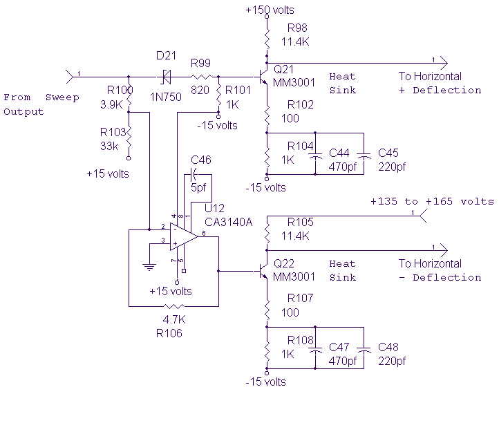
The circuit below provides the horizontal drive voltage. The supply voltage on one end, +135 to +165, is made variable for the horizontal position control. The described circuit is designed to generate a horizontal drive voltage, which is essential in...

The circuit provides a voltage gain of 20 ±0.1 dB within a frequency range of 500 kHz to 50 MHz. The low-frequency response of the amplifier can be enhanced by increasing the value of the 0.05 µF capacitor connected...
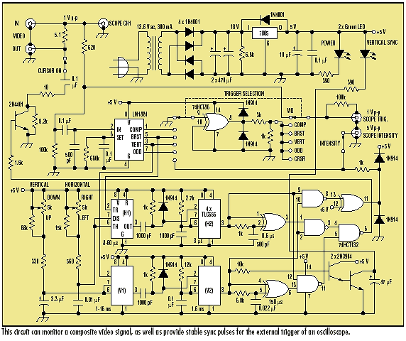
Video signals can be challenging to display on an oscilloscope. Standard trigger circuits in most oscilloscopes often struggle to achieve a stable trigger from the combined vertical and horizontal sync signals, color burst, and picture signal found in a...