
Horizontal Deflection Amplifier for Oscilloscope

The described circuit is designed to generate a horizontal drive voltage, which is essential in applications such as display technology, including CRTs (Cathode Ray Tubes) and certain types of LCDs (Liquid Crystal Displays). The supply voltage range of +135 to +165 volts indicates that the circuit operates at high voltage levels, which are typical for horizontal deflection systems in display devices.
The circuit likely incorporates a variable resistor or a potentiometer that allows for the adjustment of the voltage supplied for horizontal positioning. This feature enables fine-tuning of the horizontal position of the display, ensuring that the image is correctly centered and aligned.
Key components of such a circuit may include a high-voltage power supply, a voltage regulator or feedback control loop to maintain stability, and possibly a transformer to step up or isolate the voltage levels as required. The output stage may utilize transistors or other switching devices that can handle high voltages and currents, ensuring reliable operation under varying load conditions.
Furthermore, protection mechanisms such as diodes may be included to prevent back EMF or voltage spikes, which could potentially damage sensitive components. Additionally, filtering capacitors are essential to smooth out any fluctuations in the voltage supply, contributing to the overall stability of the horizontal drive voltage.
In summary, this circuit plays a critical role in controlling the horizontal positioning in display technologies, with a focus on providing a variable high-voltage output that can be adjusted for precise alignment of images on the screen.The circuit below provides the horizontal drive voltage. The supply voltage on one end, +135 to +165, is made variable for the horizontal position control. 🔗 External reference
Related Circuits

A simple linear voltage-controlled amplifier can be constructed with one operational amplifier (op amp) and two junction field-effect transistors (JFETs). This amplifier can achieve an 80-dB dynamic control range with less than ±0.2% linearity error for 0 V. The described...
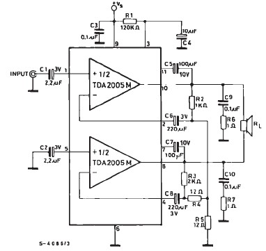
TDA2005 car audio amplifier circuit diagram electronic project using few external electronic parts The TDA2005 is a robust integrated circuit designed for audio amplification in automotive applications. This circuit diagram outlines a project for a car audio amplifier that utilizes...
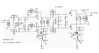
This is an RF Power Amplifier designed for low-cost QRP applications. The circuit operates over a broadband frequency range of 1.8 to 30 MHz, eliminating the need for tuning. The only adjustment required is to set the quiescent current...
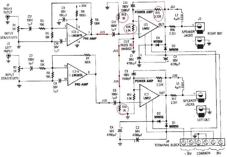
The LM12 audio amplifier circuit is designed to deliver high output power for loads with impedances of 4 ohms or 8 ohms. The maximum output power achievable by this amplifier is approximately 60 watts for a 4-ohm load and...

The general (and very basic) principle of operation is shown in Figure 1. The test signal is simply derived from the mains, and is a sinewave at 50 or 60Hz. In most locations, the sinewave will be distorted, but...
The unit is powered directly from the 120 volt AC line, with no power transformers. Filaments are wired in series, with the total adding up to 117 volts (35 + 35 + 35 + 12). The 35W4 forms a...