
2Y-2Y connection two-speed motor contactor control circuit

The circuit design depicted in Figure 3-107 integrates two operational modes controlled by distinct buttons: SBi for low-speed operation and SB2 for high-speed operation. The functionality of this circuit can be understood by examining the role of each component and the overall configuration.
In this schematic, the low-speed button (SBi) is typically connected to a resistor-capacitor (RC) network, which may introduce a delay or limit the current flow, thereby reducing the operational speed of the connected device. This ensures that the device operates smoothly at lower speeds, which may be necessary for applications requiring precision or gradual acceleration.
Conversely, the high-speed button (SB2) is designed to bypass the RC network or provide a direct connection to the power supply, allowing the device to operate at its maximum speed. This configuration is beneficial for applications where rapid response times are critical, such as in motor control or high-speed data transmission.
The circuit may also include additional components such as diodes for protection against reverse polarity, transistors for switching, and indicators (LEDs) to provide visual feedback on the operational mode selected. The design should ensure that the transition between low-speed and high-speed modes is seamless and that the circuit can handle the different current demands without overheating or failing.
Overall, the schematic serves as a versatile solution for applications requiring variable speed control, effectively allowing users to select the desired operational mode based on their specific requirements. Circuit shown in Figure 3-107. Figure, SBi is running at low speed button, SB2 for the high-speed operation button.
Related Circuits
Long-distance infrared transmitter circuit diagram. This simple circuit offers a considerable range by utilizing three infrared transmitting LEDs (IR1 through IR3) in series to enhance the radiated power. To further improve directivity and power density, the IR LEDs can...
This circuit is designed to detect the approximate percentage of salt in a liquid. After careful calibration, it can provide a quick, rough indication of salt content in liquid foods for dietary purposes. The operational amplifier IC1A is configured...
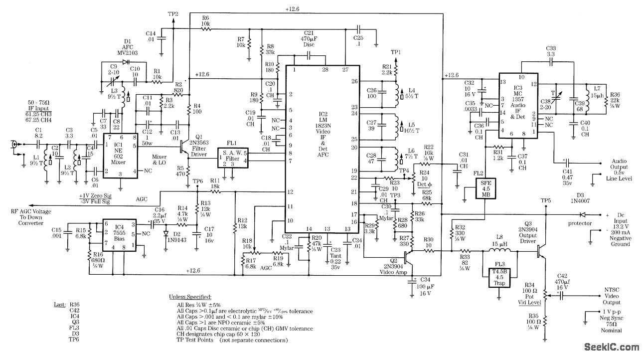
Radio-frequency schematics (also see NE602 datasheet and application note). This page contains electronic circuits related to RF receivers. This index features a broad collection of RF receiver circuits. Radio-frequency (RF) schematics are essential for designing and implementing circuits that operate...
This power supply is designed for amateur use and has been operational for over 10 years. Its design is straightforward and largely resistant to radio frequency interference (RF). The system incorporates various components, with the most significant being a...
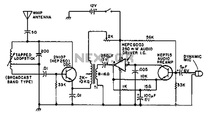
A circuit diagram of the T1 is a low-impedance output transformer, featuring a 5000-8 ohm resistor. The T1 low-impedance output transformer is designed to match the output of audio amplifiers to the impedance of loudspeakers, ensuring optimal power transfer and...
Figure 2-32 (a) illustrates the time control diagram for a motor operated by switch S1. When S1 is set to position 1, the power driver circuit supplies current to the motor, enabling it to run. When S1 is switched...