
Compound excited DC motor reversing circuit

The circuit in question is designed for a re-excitation type DC motor, characterized by its six-terminal configuration which allows for versatile control over both the armature and field windings. The armature windings, connected to terminals S1 and S2, are responsible for converting electrical energy into mechanical energy. The series field windings connected to terminals C1 and C2 provide a magnetic field that is directly proportional to the armature current, enhancing the motor's performance during varying load conditions. The shunt field windings, connected to terminals T1 and T2, provide a more stable magnetic field, which is essential for maintaining consistent motor operation.
In this design, the magnetic field direction is maintained constant for the series and shunt windings, allowing for efficient control of the armature current. By reversing the current direction in the armature windings, the motor can be operated in both forward and reverse directions. The reverse brake mode is particularly beneficial for applications requiring quick stops, as it enables the motor to decelerate rapidly by shorting the armature through a braking resistor R. This method of braking dissipates the kinetic energy of the motor as heat in the resistor, leading to a swift halt.
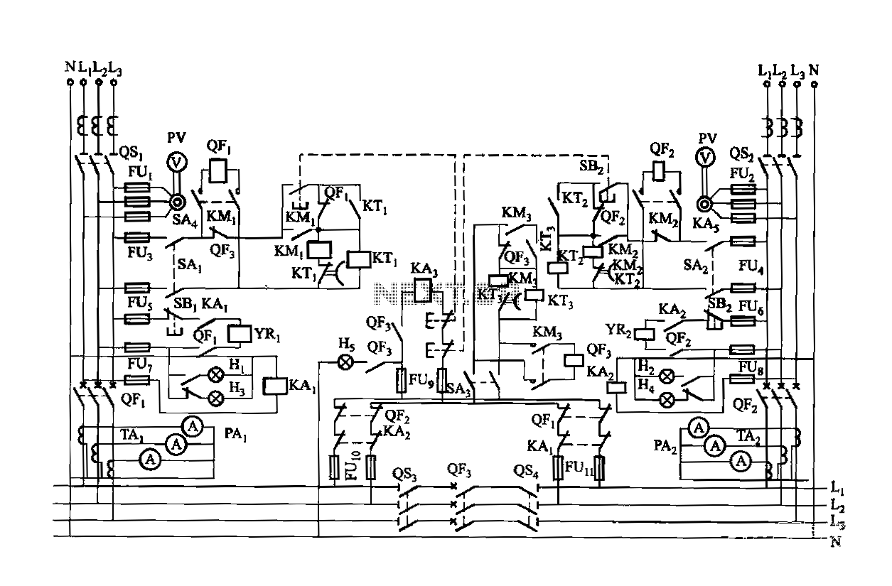
Furthermore, the circuit includes protective features such as overcurrent protection (K1) and weakening protection (K2). The overcurrent protection device (K1) safeguards the motor from excessive current that could cause overheating or damage, while the weakening protection device (K2) prevents the magnetic field from becoming too weak, which could lead to instability in motor operation. Overall, this circuit design ensures reliable and efficient operation of the re-excitation type DC motor in various applications, while also prioritizing safety and performance stability. Circuit shown in Figure 3-194. Motor is re-excitation type DC motor. The motor has six terminals, sl, S2 for the armature windings; cl, cz for the series excitation (field) win ding; Ti, Tz for the shunt (field) winding. In order to achieve positive and negative to the operation of the cl, C2 and Ti, Tz magnetic field direction is fixed, while changing the current direction of the armature S1, S2 winding. This circuit take reverse brake mode. When stopped, the motor armature ends by short braking resistor R and the motor is stopped soon. The line has overcurrent protection (KIl) and weakening protection (KI2).
Related Circuits
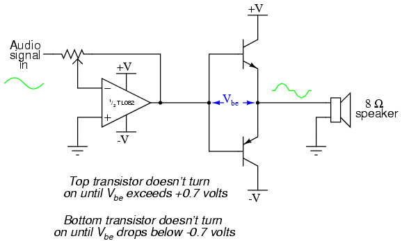
This project is an audio amplifier designed to amplify output signals from small radios, tape players, CD players, or other audio signal sources. For stereo operation, two identical amplifiers must be constructed—one for the left channel and another for...
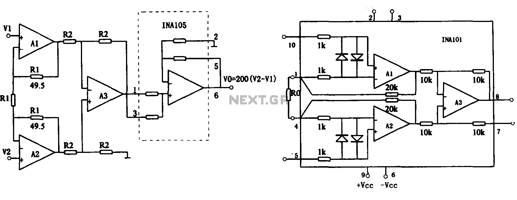
This document describes the extended common mode input voltage range of an instrument amplifier circuit. The circuit consists of three precision instrument amplifiers, A1, A2, and A3, which can be INA101 or INA102 models. The figure illustrates that A1,...
Dual power is provided for each complex, as the load is supplied through a two-way power system. In the event of a power outage, the contact switches transition from a closed position, allowing the power supply circuit to bear...
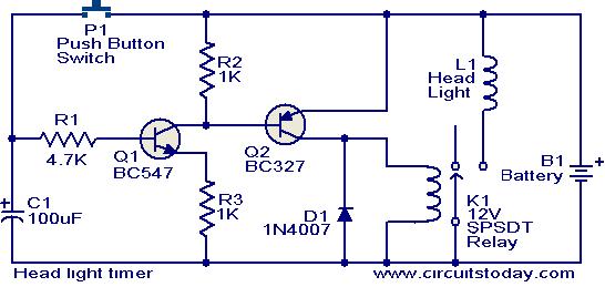
This circuit is a compact timer that keeps the headlights of a car on for approximately 1.5 minutes before turning them off. Incorporating this circuit into a vehicle allows access to dark areas without the need to return and...
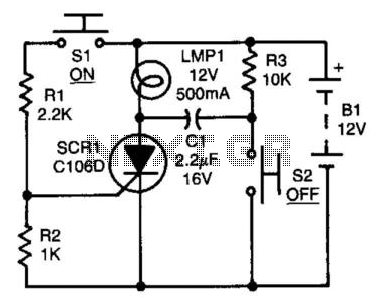
After the SCR is activated, capacitor CI charges up to nearly the full supply voltage through resistor R3 and the anode of the SCR. When switch S2 is later closed, it grounds the positive terminal of CI, causing the...
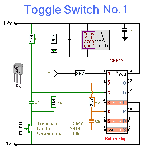
This simple circuit will energize and de-energize a relay with the push of a button. Pressing the button once will energize the relay, while pressing it a second time will de-energize the relay. The accompanying circuit provides a solid...