
Phase shift AC Circuits

In constructing an AC circuit, it is essential to understand the behavior of various components under alternating current conditions. The circuit typically consists of resistors and capacitors, where the resistors exhibit a purely resistive behavior, while the capacitors introduce reactance that causes phase shifts between voltage and current.
When measuring voltage drops across components, the use of an AC voltmeter is crucial. The voltmeter provides measurements of the root mean square (RMS) values of the voltages, which are representative of the effective values in an AC circuit. As the measurements are taken, it becomes evident that the voltage drops across the capacitors and resistors do not simply add up to the supply voltage due to the phase differences.
To analyze the circuit accurately, it is beneficial to measure voltage drops across both resistors simultaneously. This measurement confirms that the voltage drops are in phase, as their combined value equals the sum of the individual readings. A similar approach applies to capacitors, where measuring the voltage drop across both at once reveals that their waveforms are also in phase, ensuring their combined voltage drop reflects the sum of the individual capacitor voltage drops.
In the context of a 60 Hz power supply frequency, calculations of impedance for each component can be performed. The impedance (Z) of a resistor is simply its resistance (R), while the impedance of a capacitor can be calculated using the formula Z = 1/(2πfC), where f is the frequency and C is the capacitance. Once impedances are determined, voltage drops can be calculated using Ohm's Law, which relates voltage (E), current (I), and impedance (Z).
The final values obtained from these calculations should align closely with the voltmeter readings, confirming the accuracy of the measurements and the theoretical predictions of the circuit behavior. This exercise highlights the importance of considering both amplitude and phase in AC circuit analysis, providing a comprehensive understanding of voltage relationships within the circuit.Build the circuit and measure voltage drops across each component with an AC voltmeter. Measure total (supply) voltage with the same voltmeter. You will discover that the voltage drops do not add up to equal the total voltage. This is due to phase shifts in the circuit: voltage dropped across the capacitors is out-of-phase with voltage dropped acr oss the resistors, and thus the voltage drop figures do not add up as one might expect. Taking phase angle into consideration, they do add up to equal the total, but a voltmeter doesn`t provide phase angle measurements, only amplitude. Try measuring voltage dropped across both resistors at once. This voltage drop will equal the sum of the voltage drops measured across each resistor separately. This tells you that both the resistors` voltage drop waveforms are in-phase with each other, since they add simply and directly.
Measure voltage dropped across both capacitors at once. This voltage drop, like the drop measured across the two resistors, will equal the sum of the voltage drops measured across each capacitor separately. Likewise, this tells you that both the capacitors` voltage drop waveforms are in-phase with each other.
Given that the power supply frequency is 60 Hz (household power frequency in the United States), calculate impedances for all components and determine all voltage drops using Ohm`s Law (E=IZ ; I=E/Z ; Z=E/I). The polar magnitudes of the results should closely agree with your voltmeter readings. 🔗 External reference
Related Circuits

A field strength meter utilizing a biased Schottky detector employs a temperature-compensated Schottky diode within an amplified, untuned field strength indicator powered by two AA cells. This device indicates the relative field strength of RF fields ranging from a...
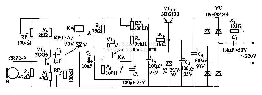
The circuit features voice switches with Figure 2109. It utilizes a single-junction transistor (VT2) and RC components to create a delay. The delay time can be adjusted using the potentiometer (RP3) or the capacitor (C3). The described circuit employs a...
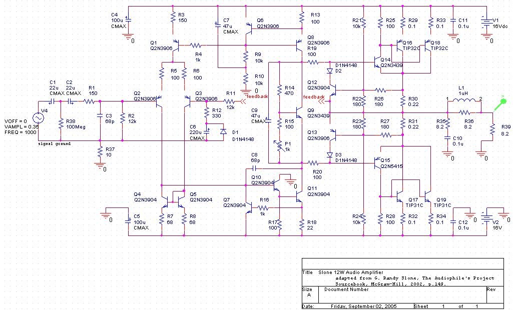
The project involves developing a 12W power amplifier circuit into a fully assembled hard-wired unit. This will require a design cycle and development sequence that includes analysis, simulation, printed circuit board (PCB) layout, board population, hard soldering, and testing....
Replacing the resistor/transistor with an n-channel power MOSFET and substituting the relay/protection diode with a light bulb results in a simplified circuit that mirrors the original design, provided one end of the light bulb is connected to +12V. If...

Connect a transformer to the motor phase line when the induced voltage is zero volts. In cases of serious imbalance in one, two, or three phases, the transformer’s induced voltage increases rapidly, which leads to an immediate rectification of...
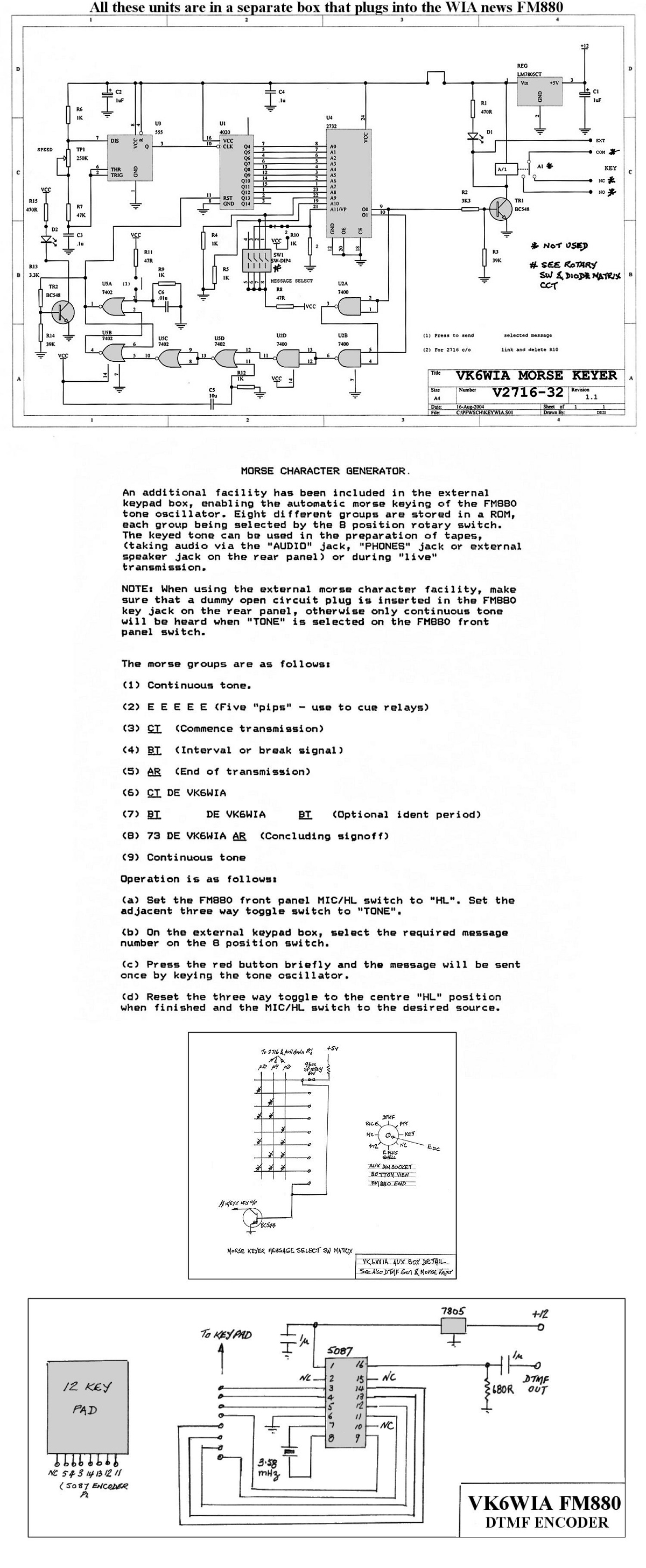
The unit is based on a PHILIPS FM880 link transceiver originally supplied to a Telecom Australia specification for telephone applications in remote areas of Australia. The FM880 is part of a family of equipment that includes the PHILIPS FM828/FM814...