
Current sensing relay

R5 needs to be chosen so that the required current is sensed. It should drop one Vbe (about 0.6V) at the required current. The MOSFET needs to be chosen with adequate voltage and current handling capacity, and of course, a heatsink may be required for the MOSFET. D3 should be a high-speed diode, with a voltage rating at least equal to the highest operating voltage the circuit will encounter. These parameters are all operating condition related. The circuit, in production, proved to be very reliable. Voltage spikes and current ratings need to be monitored. It is advisable not to operate it at low voltages, less than the solenoid voltage plus 15V, as the MOSFET goes into linear mode. This is not immediately damaging to the MOSFET, but it can generate excessive heat. Therefore, it is preferable to control the relay by activating and deactivating the controller rather than connecting and disconnecting the power. Methods for implementing this control could be developed in the future.It operates by PWM (Pulse Width Modulation) - well, actually by PFM - Pulse Frequency Modulation. At power up, C1 charges up via D1 and R1. R2 will conduct, pulling the base of the emitter follower, Tr2, up and feeding gate voltage to the MOSFET. Tr4. Clearly the circuits in an analogue region during power-up, but as this is intended for use on a high voltage supply, power-up is pretty quick.
As Tr4 conducts, current is fed through R5 and the coil of the Solenoid. The current builds up, until the voltage across R5 becomes high enough to turn on Tr1. Tr1 and Tr3 are a complementary feedback pair, so when Tr1 conducts, they turn each other on in a snap action switch and the MOSFET gate gets turned hard off. The current in the solenoid coil is forced (by the inductance) to keep flowing. It does so via D3 and R4. But the current into Tr1's base is the sum of the currents through R4 and Tr3. R2's current flows through Tr1, so none flows in Tr2, so Tr3 current (after the bate has discharged) is only the current through R3.
So the current through R5 must drop by this amount before it is insufficient to keep Tr1 conducting. This current is caused by the sensed relay current flowing through R5, so the ratio of R3 to R4 sets the hysteresis. When there is insufficient current to keep Tr1 conducting, it turns off and the gate is again pulled high by R5 and Tr2, turning the MOSFET on.
It slams the supply voltage across the relay coil, building up the current. Clearly the rate of current build-up will depend on the supply voltage, so at low voltages, the MOSFET turns on for a longer time and at high voltages, a shorter time. The time during which the MOSFET is off is dependant on the relay coil and is constant, whilst the on time varies, altering the frequency.
R5 needs to be chosen so that the required current is sensed. It should drop one Vbe (about 0.6v) at the required current. The MOSFET needs to be chosen with adequate voltage and current handling capacity, and of course you may need to heatsink the MOSFET. D3 should be a high speed diode, with a voltage rating at least equal to the highest operating voltage the circuit will encounter.
These things are all operating condition related, so I'll have to leave them to you! Constraints The circuit, in production, proved to be very reliable. Clearly you need to watch voltage spikes and current ratings. You should also not try to operate it at low voltages, say less that the solenoid voltage plus 15v, as the MOSFET goes into linear mode. This is not immediately damaging to the MOSFET, but it can get hot. For this reason, it is probably best not to switch the relay by connecting and disconnecting the power, but by activating and deactivating the controller.
Methods of doing this could be added later. 🔗 External reference
Related Circuits

This circuit design for a low current relay is intended for use in battery-operated electronic devices, with an operating current in microamperes (µA). It utilizes a bistable relay and additional components to enable the relay to function similarly to...

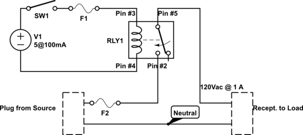
The schematic below illustrates four methods of controlling a relay with a digital logic signal. Figure A can be used in most cases where the relay coil requires 100 mA or less and the input current is 2 milliamps...
Capacitive proximity sensing has gained significant interest among audiences over the past year. At the end of this article, a list of related articles published at Planet Analog is provided for further reading. A simple proximity sensor is designed...
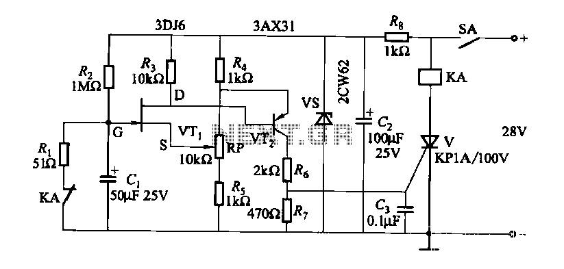
FET relay circuit 2 is essentially a JS-20 time relay circuit. When the switch SA is open, the relay device KA remains in the released state. Once switch SA is closed, the delay period begins. After a specified duration,...
A single-pole double-throw (SPDT) switch is used to control a relay. When the relay is energized, it produces a cycling sound, which is undesirable. The goal is to have the switch operate normally in the 'on' position and return...
The headlights of a 2001 Chevy S10 sometimes function and sometimes do not, along with the dashboard indicator light. All other lights are operational. The headlight switch, fuse, and relay have been replaced, and the headlight bulbs have been...